
Доступно к заказу
Цена по запросу
И выбери подходящего.
Description
- Linear modules with Ball Rail System and Precision Ball Screw Assembly
- Available in five sizes in lengths up to 5400 mm
- Repeatability of up to ± 05 mm
- Protection of Ball Rail System and Ball Screw Assembly by a sealing strip (bellows cover on MKK-165)
- Screw support for the realization of high speeds on long assembly lengths. Suitable for horizontal installation (for MKK-080, MKK-110 and MKK-140, product generation 3)
Features
- The Rexroth Ball Rail System and the Rexroth precision Ball Screw Assembly feature one-point lubrication from both sides; one-point lubrication is only suitable for grease lubrication with a manual grease gun
- Individual lubrication versions for connection to one-point lubrication systems (only for product generation 3)
- Rexroth precision ball screw assembly in rolled design with backlash-free, cylindrical single nut, tolerance grade 7, and leads of up to 40 mm
- Attachments are fastened to the carriage using T-slots or threaded holes
- Ball Guide Rail and Ball Screw with corrosion-resistant coating, Ball Runner Block made of corrosion-resistant steel (only for product generation 3)
- Absolute position measuring system IMS-A directly integrated into the guide system (for MKK-080, MKK-110 and MKK-140, product generation 3)
- Motor attachment via mount and coupling or via timing belt side drive
- Servo motor with multi-turn encoder, 1-cable or 2-cable connection, with or without holding brake
- Magnetic field sensors can be mounted without additional attachments directly onto the profile body (only for product generation 3)
- Switch (proximity or mechanical), cable duct, socket-plug and extension cable
- Extensive accessories for connection and clamping elements
- Nameplate with technical parameters for easy start-up
Product description
The new product generation 3 (MKX-XXX-NN-3) of the Rexroth Linear Modules is based on the consistent further development of the previous series. The usual Rexroth performance features have been improved once again with consideration of backward compatibility.
Rexroth Linear Modules of product generation 2 (MKX-XXX-NN-2) are precise, ready-to-install guide systems with high-performance features in compact dimensions.
Product description MKK-xxx-NN-3
Structural design
- Ready-to-install linear modules in any length up to Lmax
- Extremely compact extruded aluminum frame with integrated Rexroth ball rail systems
- Carriages made of aluminum with T-grooves or threaded holes and with centering holes in each case
- Individual lubrication versions for connection to central lubrication systems
- Driven by precision Rexroth ball screw assembly (BASA) in rolled design, optionally in tolerance class T7 or T5 according to ISO 3408-3 with zero-backlash cylindrical single nut
- Sealing strip (plastic strip for MKK-040 and MKK-065, corrosion resistant steel strip for MKK-080, MKK-110 and MKK-140)
Attachments (range of accessory products)
- Sensors and extension cables
- Switches (proximity or mechanical)
- Cam switch
- Socket and plug
- Aluminum profile cable channel
- Clamping fixtures and sliding blocks
- Connecting shafts
- Connecting technology for linear motion systems

| 1) | Carriage with thread |
| 2) | Carriage with T-slots |
Screw support (SPU) for MKK-080-NN-3, MKK-110-NN-3 and MKK-140-NN-3
The Screw Support (SPU) offers the following advantages:
- Screw support for horizontal applications (in preparation for vertical applications)
- Screw support can be selected as standard option via the option number.
- A maximum of two screw support pairs is possible.
- High speed over long lengths of up to 5400 mm.
- Guide of the screw supports in the main body.
- Screw supports are maintenance-free.
- Screw supports are protected by optionally selectable sealing strip.

Integrated Measuring System for MKK-080-NN-3, MKK-110-NN-3 and MKK-140-NN-3
The IMS-A measuring system offers the following advantages:
- No additional space required.
- No external mounting surfaces required for the measuring system.
- No measuring inaccuracies due to deviations in parallelism between the measuring system and the guide system
- Full integration of the measuring system components into the guide means no complex assembly or tuning work is needed
- The runner block, measuring head and guide rail with scale can be replaced individually during servicing.
- Interfaces: HIPERFACHE or DRICE-CLiQ.
- Connection cable directly on the side of the carriage.


| 1) | Motor mounting with timing belt side drive |
| 2) | Motor mounting with flanged-type coupling |
Material pairing
ALST:
- Main body, carriage and end plates made of anodized aluminum (AL)
- MKK-065/-080/-110/-140: Ball rail, ball runner block and ball screw assembly made of rolling bearing steel (ST)
- MKK-040: Ball rail and ball runner block of rust and acid resistant material. Ball screw assembly made of rolling bearing steel (ST)
- Angular-contact ball bearing and grooved ball bearing of the screw drive bearing made of rolling bearing steel
ALCR:
- Main body, carriage and end plates made of anodized aluminum (AL)
- MKK-065/-080/-110/-140: Ball rail and ball screw assembly made of rolling bearing steel with corrosion resistant coating, matte-silver finish, hard chrome plated (Resist CR), ball runner block from corrosion resistant steel (Resist NR)
- MKK-040: Ball rail and ball runner block of rust and acid resistant material. Ball screw assembly made of rolling bearing steel with corrosion resistant coating, matte-silver finish, hard chrome plated (Resist CR)
- Angular-contact ball bearing and grooved ball bearing of the screw drive bearing made of rolling bearing steel
Lubrication variants
LSS: (Initial lubrication done at the factory)
- Initial standard greasing done at the factory, suitable for normal ambient conditions.
- Simple relubrication via manual grease gun.
MKK-065, MKK-080, MKK-110, MKK-140:
- Grease lubricant Dynalub 510, lithium-based high-performance grease of the NLGI grade 2 according to DIN 51818 (KP2K-20 according to DIN 51825)
MKK-040:
- Grease lubricant Dynalub 520, lithium-based high-performance grease of the NLGI grade 00 according to DIN 51818 (GP00K-20 according to DIN 51826)
LPG: (Corrosion prevention, no initial lubrication)
- Linear module without initial greasing done at the factory.
- Ball rail system and ball screw assembly only with corrosion prevention
- Basic lubrication required
LCF: (prepared for connection to central lubrication systems with liquid grease)
- for liquid grease, NLGI grade 00 lithium-based high-performance grease according to DIN 51818 (GP00K-20 according to DIN 51826)
- Liquid grease lubrication via single-line piston distributor system only
- Basic lubrication required
LCO: (prepared for connection to central lubrication systems with oil)
- ball runner block and ball screw drive nut with integrated non-return valves
- Only use oil lubrication with single-line total-loss lubrication systems via piston distributors.
- Basic lubrication required
Product description MKK-165-NN-2
Linear modules with Rexroth ball rail system and ball screw assembly for high positioning precision and reproducibility as well as thrust forces.
Structural design
- Ready-to-install linear modules in any length up to Lmax
- Extremely compact extruded aluminum frame with integrated Rexroth ball rail systems
- Drive via Rexroth ball screw assembly set to zero-clearance (also available without a drive)
- Carriages made of aluminum with T-grooves or threaded holes (depending on the size)
- Cover provided by the bellows
Attachments
- Switches (proximity or mechanical)
- Socket and plug
- Aluminum profile cable channel
Attachments (range of accessory products)
- Clamping fixtures and sliding blocks
- Connecting shafts
- Connecting technology for linear motion systems
- Sensors and extension cables
MKK-165 with bellows

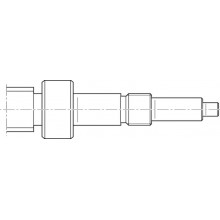
Structure and attachments

Structural design
1 Ball screw assembly (BASA) with zero-backlash cylindrical single nut
2 End block fixed bearing
3 Cover strip for MKK-040/-065/-080/-110/-140
4 Carriage with runner blocks
5 Strip fixing
6 End plate floating bearing
7 Main body
Attachments
8 Switch bracket
9 Proximity switch
10 Mechanical switch
11 Cable channel
12 Socket/plug
13 Bellows cover for MKK-165
14 Magnetic field sensor

15 Mount
16 Servo motor
17 Timing belt side drive
Technical data

Maximum values for each size
| Size | MKK-040-NN-3 | MKK-065-NN-3 | MKK-080-NN-3 | MKK-110-NN-3 | MKK-140-NN-3 | MKK-165-NN-2 | |
| Cgw | N | 3750 | 16000 | 38000 | 46500 | 59300 | 84100 |
| Cbs | N | 4100 | 13320 | 15480 | 34200 | 54000 | |
| Cfb | N | 4000 | 13400 | 16900 | 26000 | 27000 | 29000 |
| Mt | Nm | 22.3 | 154 | 487 | 666 | 1020 | 1803 |
| ML | Nm | 93.8 | 533 | 1843 | 2235 | 3190 | 5130 |
| Mx max | Nm | 11 | 62 | 195 | 264 | 409 | 723 |
| My max | Nm | 53 | 213 | 737 | 894 | 1275 | 2085 |
| Mz max | Nm | 53 | 213 | 737 | 894 | 1275 | 2085 |
| Fy max | N | 1875 | 6400 | 15200 | 18600 | 23700 | 34100 |
| Fz1 max | N | 1875 | 6400 | 15200 | 18600 | 23700 | 34100 |
| Fz2 max | N | 1875 | 6400 | 15200 | 18600 | 23700 | 34100 |
| Lmax | mm | 1000 | 2500 | 3400 | 5400 | 4000 | |
| amax | m/s² | 50 | |||||
| vmax | m/s | 1 | 1.21 | 2.5 | 1.6 | 2.5 | 1.47 |
| Maximum values depends on the selected configuration. |
Legend
| Symbol | Description | Unit |
| Cgw | Dynamic load capacity, linear guide | N |
| Cbs | Dynamic load capacity, ball screw drive | N |
| Cfb | Dynamic load capacity, fixed bearing | N |
| Mt | Dynamic torsional moment load capacity | Nm |
| ML | Dynamic longitudinal moment load capacity | Nm |
| Mx max | Maximum admissible torsional moment around the x-axis | Nm |
| My max | Maximum admissible torsional moment around the y-axis | Nm |
| Mz max | Maximum admissible torsional moment around the z-axis | Nm |
| Fy max | Maximum dynamic load in y-direction | N |
| Fz1 max | Maximum dynamic load in z-direction | N |
| Fz2 max | Maximum dynamic load in z-direction | N |
| Lmax | Maximum length | mm |
| amax | Maximum acceleration travel | m/s2 |
| vmax | Maximum permissible speed | m/s |
Mounting
Mounting
General information
The linear modules are mounted using various fastening elements:
- Clamping fixtures
- Sliding blocks for size -110 and up
- Square nuts
- Spring nuts
- Screws for T-slots as per DIN 787 (no picture).
Length depends on base.
When mounting Linear Modules, please note the maximum tightening torques listed in the table.
Mounting with clamping fixtures

Mounting with sliding blocks

| 1) | 85 (size .. -110) 120 (size -165) |
| Size | A | B | C |
| (mm) | (mm) | (mm) | |
| -040 | 52,2 | 65,5 | - |
| -065 | 81,0 | 95,0 | - |
| -080 | 96,0 | 110,0 | - |
| -110 | 132,0 | 150,0 | 85,0 |
| -140 | 167,0 | 193,0 | 105,0 |
| -145 | 172,0 | 198,0 | 78,0 |
| -165 | 192,0 | 218,0 | 120,0 |
Do not support the linear module on end enclosures, end blocks or on end plates!
The frame is the load-bearing part!

Tightening torques of fastening screws
with friction factor 0.125 strength class 8.8
 | 8.8 | M4 | M5 | M6 | M8 | M10 | M12 |
 | (Nm) | 2,7 | 5,5 | 9,5 | 23 | 46 | 80 |
Overview of the switching system
1 Socket and plug
2 Mechanical switch with attachments
3 Proximity switch
4 Switch bracket
5 Mounting channel / cable channel
6 Magnetic field sensor with fixed potted cable
(Reed/Hall sensor (for mounting channel))
7 Reed/Hall sensor with plug and sensor holder
7a: Magnetic sensor
7b: Sensor holder incl. set screws (loose) and square nut
7c: Cable holder (3 pcs) incl. set screw (loose)
7d: M8x1 plug (3-pin)
8 Magnetic switch with M8x1 plug
9 Clamping screw
10 Sliding block
Further switch connection options (MKK/MKR-040-NN-3)
Magnetic field sensor (6) and mounting channel (5)
Mounting instructions:
A mounting channel is needed to fasten the magnetic field sensors and cable guides.
This is suspended at the side in the upper slot at the linear module MKK / MKR-040 and secured with set screws.
The magnetic field sensors are pushed into the top (MKK) or bottom T-grooves (MKR) in the mounting channel and
fixed with set screws. The switch activator is a magnet (on both sides) that is integrated in the carriage (no switch bracket necessary). The switch activation points can be positioned anywhere along the stroke. For position of solenoid switch, see the linear module instructions R320103169.

Switch connection MKK/MKR-040-NN-3
Magnetic sensor with M8x1 plug, switch mounting plate and cable holder
The switch activator is a magnet (on both sides) that is integrated in the carriage (no switch bracket necessary). The switch activation points can be positioned anywhere along the stroke. For position of solenoid switch, see the linear module instructions R320103169.
Mounting instructions:
The magnetic sensor is inserted into the corresponding slot of the sensor holder and fixed by turning the clamping screw in the sensor mount.
Sensors may only be mounted on one side (left or right) of the linear module and should not be installed until the linear module has been screwed down on its substructure. For a description of the mounting procedure and determination of the switching positions, see the mounting instructions for linear modules. See "Accessories" section for technical data.

Switch mounting MKK/MKR/MLR-xxx-NN-x
MKK/MKR-xxx-NN-3

MKK/MKR/MLR-xxx-NN-x

Proximity sensors, mechanical switches and accessories (MKK/MKR/MLR)
Mounting instructions:
The mechanical switches, the proximity sensors and the socket with plug and cable channel are fastened with attachments in T-grooves of the main body. Switch activation is carried out by a switch bracket on the carriage.

| Position | Name | Size -065/-080/-140 /-145-NN-3 | -110-NN-3 | -165-NN-2 |
| Material number | ||||
| 1 | Socket-plug | R117500153 | ||
| 2 | Mechanical switch | see accessories | ||
| Mechanical switch with attachments | R117500151 | |||
| 3 | Proximity sensor | see accessories | ||
| - Attachment parts without sensor | R117500152 | R117520152 | R117500152 | |
| 4 | Switching angle | R117500149 | R117500150 | |
| 5 | Cable duct | R039662017 | ||
| These switching versions can only be ordered with these material numbers. |
| Proximity sensor with additional attachment for | Proximity sensor with additional attachment for | Mechanical switch with attachment for |
 |  |  |
| 1) | Cable length: 3 m |
Socket and plug, cable duct
Attach the socket to the side with the most switches. The socket and plug are not pre-wired. The variable sliding attachment allows switching positions to be optimized during start-up. The plug can be mounted in three directions.
Cable duct
The cable duct is fastened in the T-slots on the side of the frame. Fastening screws widen the profile and ensure that the cable duct is securely mounted.
See the illustration for the position of the slot.
The cable duct will accommodate up to two cables for mechanical switches and three cables for proximity switches.
Fastening screws and cable grommets are included.

Mounting examples of switches
Determination of the switching position
Switching distance: The switching distance is the distance between the carriage center (TM) and the zero point (0) when a switch is actuated (indicated in mm). Example of a mechanical limit switch (assuming the zero point is at L/2):
Maximum switching distance = 0.5 x (max. travel distance) – excess travel = 0.5 x effective stroke
For safe operation of the linear module the excess travel must be greater than the braking path.
For MKR... and MLR...: The acceleration travel sa can be assumed as the reference value for the braking distance.
For MKK...: In most cases, the following is sufficient as a guideline value for the excess travel (braking path): Excess travel = 2 x screw lead P.
Note the smallest possible switching distance (determined by attachments):
mechanical-mechanical = 60 mm; mechanical-proximity = 45 mm; proximity-proximity = 28 mm.
for MKR-145: mechanical-mechanical = 62 mm; mechanical-proximity = 49 mm; proximity-proximity = 35 mm
The switches as well as socket with plug are fixed in the upper T-slots of the frame and actuated by a switch tab on the carriage.
Mounting side of the switches:

| 1) | links (L) |
| 2) | right (R) |
| 3) | Direction of travel |
| 4) | 0.5 x stroke |
| 5) | Excess travel |
| 6) | 0.5 x max. travel path |

Accessories
Clamping fixtures for Linear Modules

Clamping fixtures for Linear Modules
Sliding blocks and springs for Linear Modules

Sliding blocks and springs for Linear Modules
Anchor strips for Linear Modules

Anchor strips for Linear Modules
Centering rings for Linear Modules

Centering rings for Linear Modules
Square nuts for Linear Modules

Square nuts for Linear Modules
Cable duct

Cable duct
Frequency meter

Frequency meter
Magnetic sensor with free line end

Magnetic sensor with free line end
Magnetic sensor with M8x1 plug

Magnetic sensor with M8x1 plug
Magnetic sensor with plug and sensor mount

Magnetic sensor with plug and sensor mount
Proximity sensor with free line end

Proximity sensor with free line end
Proximity sensor with M8x1 plug

Proximity sensor with M8x1 plug
Additional components for inductive sensor

Additional components for inductive sensor
Magnetic sensors

Magnetic sensors
Mechanical switch

Mechanical switch
Mechanical switch with M8x1 plug

Mechanical switch with M8x1 plug
Additional components for mechanical switch

Additional components for mechanical switch
Extension pieces - assembled on one side

Extension pieces - assembled on one side
Adapter

Adapter
Socket and plug
R117560102

Socket and plug
R117560102
Socket and plug
R117500153

Socket and plug
R117500153
Mounting duct

Mounting duct
Switching angle

Switching angle
Nozzle pipe
R3455 031 06

Nozzle pipe
R3455 031 06
- For manual grease guns
- For the lubrication of funnel-type and ball-type lube nipples
Safety Instructions
Required and supplementary documentation
For further instructions and information, please refer to the documentation for this product.
You can find PDF files of these documents on the Internet at www.boschrexroth.com/mediadirectory.
We would also be happy to send you the documents that you want.
If you are unsure about using this product, please contact Bosch Rexroth.
Ordering codes
Order overview
| Size | Part number | Short product name | CAD data | Buy |
| MKK-040-NN-3 | R116066013 | MKK-040-NN-3 | ||
| MKK-065-NN-3 | R116006013 | MKK-065-NN-3 | ||
| MKK-080-NN-3 | R116016013 | MKK-080-NN-3 | ||
| MKK-110-NN-3 | R116026013 | MKK-110-NN-3 | ||
| MKK-140-NN-3 | R116046013 | MKK-140-NN-3 | ||
| MKK-165-NN-2 | R116036000 | MKK-165-NN-2 |
Explanation of short product name
| Linear Module MKK example | MKK-110-NN-3 | |
| System | M = | Linearmodule |
| Linear guide | K = | Ball Rail System |
| Drive | K = | Ball screw assembly |
| Size | 110 = | 040/065/080/110/140/165 |
| Version | NN = | Normal version |
| Generation | 3 = | Product generation 3 |
Downloads
| Declaration of Incorporation for single axis Linear Motion Systems Certificate | R320103141 | 2020-06-01 | All languages | PDF | 409k Product Groups: Linear axes and electromechanical cylinders | |
| Safety Instructions for Linear Motion Systems Manual | R320103152_en | 2015-01-01 | English | PDF | 593k Product Groups: Linear axes and electromechanical cylinders | |
| Linear Modules MKK/MKR/MLR -040/-065/-080/-110/-140/-145-NN-3/-165-NN-2 Manual | R320103169_EN | 2021-11-01 | English | PDF | 6.9MB Product Groups: Linear Modules only available as PDF | |
| Linear Modules MKK / MKR / MLR Catalog | R999000496 | 2021-03-01 | English | PDF | 17.5MB Product Groups: Linear Modules |


Цена по запросу

Цена по запросу


Нет отзывов об этом товаре.