
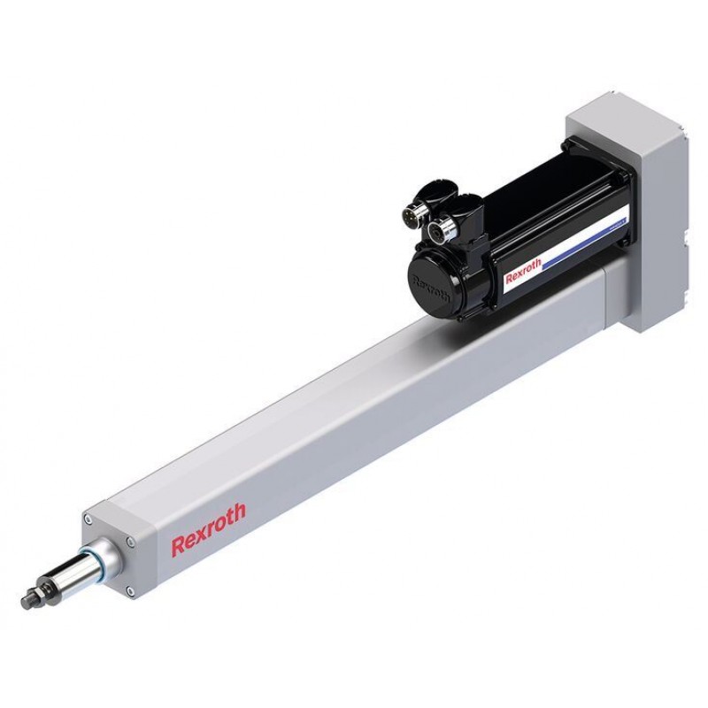
Доступно к заказу
Цена по запросу
И выбери подходящего.
Description
- High-precision ball screw assemblies: for high performance with maximum cost-effectiveness
- Complete building system with great variability: can be adapted to a wide range of applications
- Complete turn-key system: minimal construction and installation effort
- The smart, freely programmable drive system allows the realization of complex travel profiles (parameters for force, position and travel speed can be set as required over the complete working travel range).
- Optimized lubrication concept: optional connection to a one-point lubrication system reduces downtime.
- High-precision ball screw assemblies: for high performance with maximum cost-effectiveness
- Hygienic design
- Complete turn-key system: minimal construction and installation effort
- Complete building system with great variability: can be adapted to a wide range of applications
Features
- Good sealing: sealed against dirt and water from outside and lubrication leakage from the cylinder by selecting the IP65 rating option
- Hygienic design: high resistance to chemicals and cleaning agents by selecting the IP65 + R (resistant) rating option
- Optional protection class IP65 for sealing against dirt and water ingress or protection class IP65 +R (resistant) for additional high chemical resistance
- Corrosion resistant stainless steel piston rod
- Suitable for pulse-controlled central lubrication systems
- Wide range of accessories
Product description
Hygienic, flexible, energy-efficient. Its high variability makes the Electromechanical Cylinder so interesting for many industries and applications. By using the available configuration options, a cheaper, simpler base cylinder can be adjusted to virtually any customer requirement: chemical resistant, with perfect sealing and a high IP type of protection. All these properties ensure a long life – even under harsh industrial conditions. The powerful Electromechanical Cylinder always performs very efficiently. The resulting energy saving potential makes it an economical alternative to pneumatic systems.
The mechanical system in the Electromechanical Cylinder EMC is based on proven Rexroth Ball Screw Assemblies in a wide range of diameter and lead combinations. The Rexroth Ball Screw Assembly converts torque into linear motion with high mechanical efficiency. During this process, the piston rod fastened to the Screw Drive nut is extended and retracted. Both the Screw Drive nut and the piston rod are guided in the housing and cannot twist.
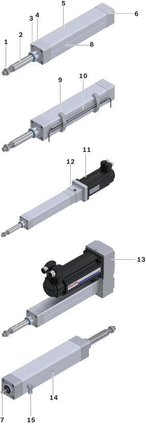
Structural design
1 Hexagon nut
2 Piston rod (stainless steel)
3 Cylinder screw (for mounting fastening element and motor attachments)
4 Cover
5 Protective profile
6 Rear end cap
7 Screw journal
8 Groove for sensor profile (opposite the lube nipple)
Attachments
9 Retaining bracket (for sensor profile)
10 Sensor profile
11 Motor
12 Mount and coupling
13 Timing belt side drive
14 Lube nipple
15 Port for pressure compensation
Structure of the EMC
Technical data
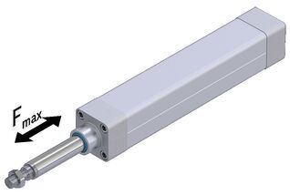
Note:
Fmax and vmax are dependent on installation and from the selected configuration of the actuator.
Legend
| Symbol | Description | Unit |
| C | Dynamic load capacity | N |
| Fmax | Maximum permissible axial force | N |
| amax | Maximum acceleration travel | m/s2 |
| vmax | Maximum permissible speed | m/s |
| smax perm | Maximum permissible travel range | mm |
Maximum values for each size
| Size | 32 | 40 | 50 | 63 | 80 | 100 | 100-XC | |
| C | N | 4100 | 13300 | 15400 | 17200 | 26000 | 42100 | 104900 |
| Fmax 1) | N | 1200 | 4500 | 7800 | 15900 | 22000 | 29000 | 56000 |
| amax | m/s² | 50 | 22 | |||||
| vmax 1) | m/s | 1.13 | 1.23 | 1.27 | 1.38 | 1.6 | 1.47 | 1 |
| smax perm | mm | 750 | 900 | 1200 | 1500 | |||
| 1) | Force or torque and speed can be limited by the motor. |
Diagrams/characteristic curves
Axial load on the cylinder mechanics (sizes EMC-32 to EMC-63)
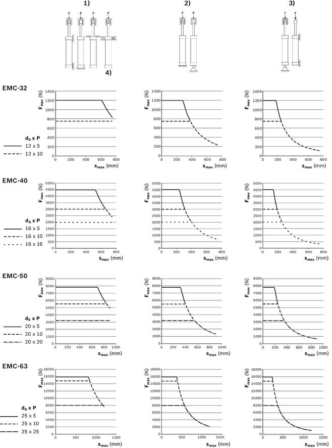
| 1) | Case I |
| 2) | Case II |
| 3) | Case III |
| 4) | only allowed vertically |
| Fmax = maximum permissible axial force (N) | |
| smax = maximum travel path (mm) |
Axial load on the cylinder mechanics (sizes EMC-80 to EMC-100XC)
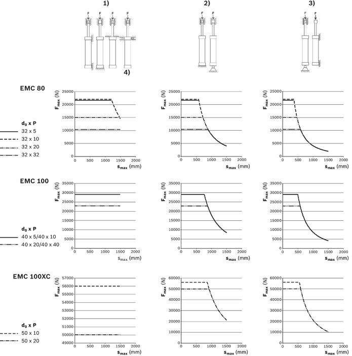
| 1) | Case I |
| 2) | Case II |
| 3) | Case III |
| 4) | only allowed vertically |
| Fmax = maximum permissible axial force (N) | |
| smax = maximum travel path (mm) |
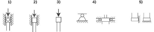
| 1) | Piston rod in swivel bearings |
| 2) | Piston rod with linear travel range |
| 3) | Piston rod free |
| 4) | Swivel mount |
| 5) | Fixed mount |
Service life
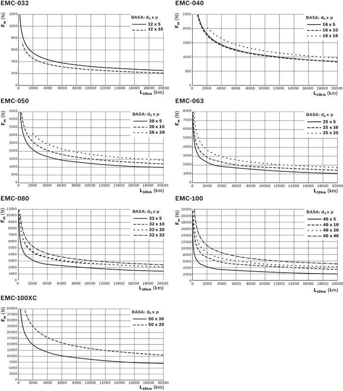
| The stated values comply with the specified relubrication intervals(see “Maintenance” chapter). | |
| For calculation of the equivalent dynamic axial load Fm see "Project planning instructions" chapter. | |
| Fm = equivalent dynamic axial load (N) | |
| L10km = nominal service life (km) |
Permissible travel speeds
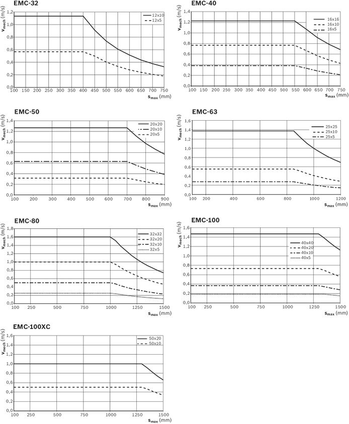
| vmech = maximum permissible speed of the mechanism (m/s) | |
| smax = maximum travel distance (mm) |
Loading of the piston rod (sizes EMC-32 to EMC-63)
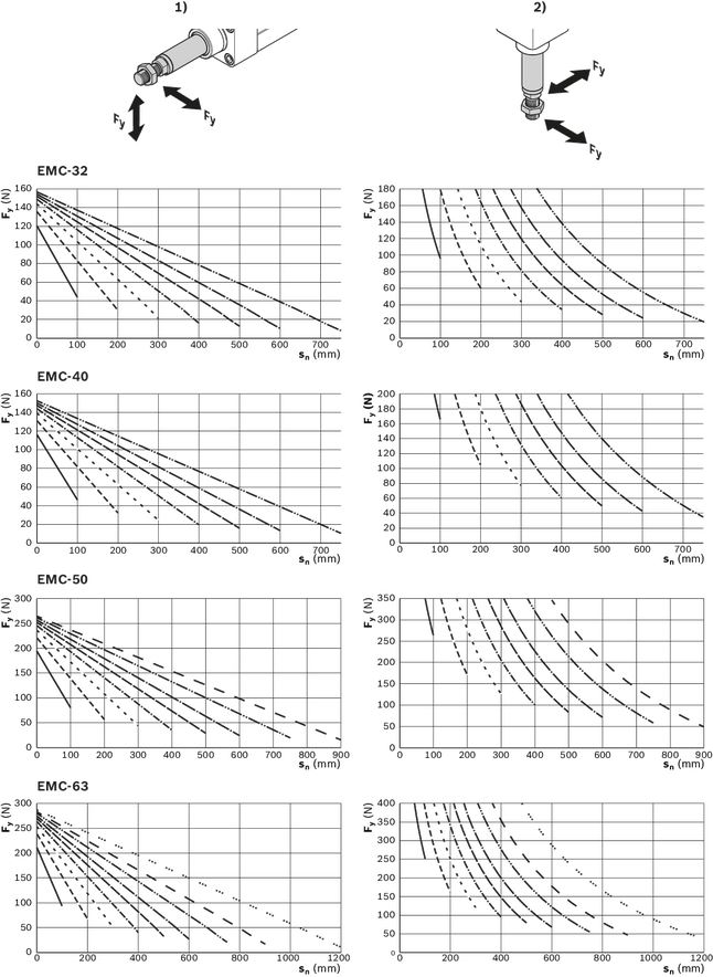
| 1) | Horizontal installation |
| 2) | Vertical mounting |
| Fy = lateral force (N) | |
| sn = position of the piston rod (mm) |
Loading of the piston rod (sizes EMC-80 to EMC-100XC)
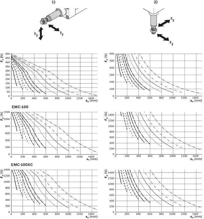
| 1) | Horizontal installation |
| 2) | Vertical mounting |
| Fy = lateral force (N) | |
| sn = position of the piston rod (mm) |
Diagrams are valid for:
- 25% of Fmax
- a speed of 0.5 m/s
Characteristics for smax
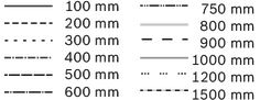
Definition smax/sn
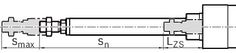
| 1) | smax = maximum travel path (mm) |
| 2) | sn = position of the piston rod (mm) |
| 3) | LZS = Retracted position of the piston rod (mm) |
Mounting
Mounting
Accessories
Motors and controllers
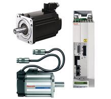
Motors and controllers
Flexible coupling
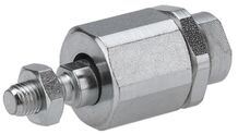
Flexible coupling
- Group 2, option 04
- Material: galvanized steel
- radial clearance 0 ... 2 mm
Flexible coupling with mounting plate
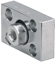
Flexible coupling with mounting plate
- Group 2, option 03
- Material: galvanized steel
Flange mounting
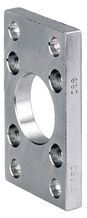
Flange mounting
- Group 3, option 04
- Material: galvanized steel
Foot mounting for mounting on the cover or timing belt side drive
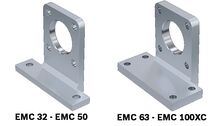
Foot mounting for mounting on the cover or timing belt side drive
- Group 3, option 06/group 5, option 06
- Material: galvanized steel
Foot mounting with centering ring for foot mounting
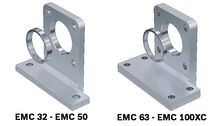
Foot mounting with centering ring for foot mounting
- Group 5, option 05
- Material: galvanized steel
Clevis mount with force measuring bolts
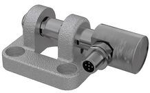
Clevis mount with force measuring bolts
- Group 1, option 02; group 5, option 10
- Material: Aluminum / galvanized spheroidal graphite iron
Clevis mount on the timing belt side drive
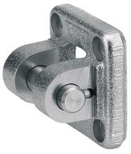
Clevis mount on the timing belt side drive
- Group 1, option 01; group 5, option 08
- Material: Aluminum / galvanized spheroidal graphite iron
Clevis mount
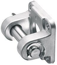
Clevis mount
- Group 5, option 07
- Material: Aluminum / galvanized cast iron with spheroidal graphite cast iron
Fork clevis with internal thread
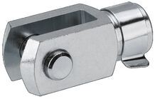
Fork clevis with internal thread
- Group 2, option 02
- Material: galvanized steel
Female spherical rod end bearing, galvanized steel
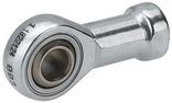
Female spherical rod end bearing, galvanized steel
- Group 2, option 01
- Material: galvanized steel
Female spherical rod end bearing, stainless steel
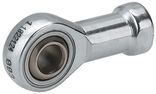
Female spherical rod end bearing, stainless steel
- Group 2, option 07
- Material: Stainless steel
Swivel mount for force measuring bolt
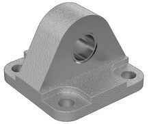
Swivel mount for force measuring bolt
- Group 6, option 05
- Material: Aluminum
Swivel bearing
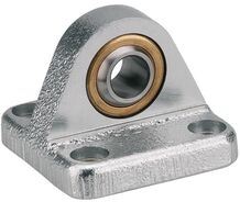
Swivel bearing
- Group 6, option 04
- Material: Aluminum / galvanized cast iron with spheroidal graphite cast iron
Swivel bearing, high
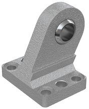
Swivel bearing, high
- Group 6, option 03
- Material: galvanized cast iron with spheroidal graphite
Bearing for trunnion
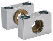
Bearing for trunnion
- are included in group 3, option 03, group 5, option 03
- Material: galvanized steel, with sockets made from sintered bronze
Bearing block
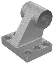
Bearing block
- Group 6, option 01
- Material: galvanized cast iron with spheroidal graphite
Nut, galvanized steel
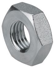
Nut, galvanized steel
- Group 2, option 05
- Material: galvanized steel
Nut, stainless steel
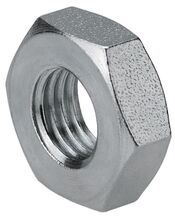
Nut, stainless steel
- Group 2, option 06
- Material: Stainless steel
Swivel flange
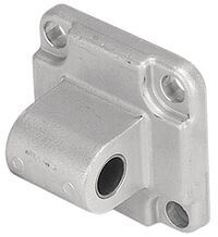
Swivel flange
- Group 6, option 02
- Material: Aluminum / galvanized cast iron with spheroidal graphite cast iron
Trunnion for cover
(only for vertical Electromechanical Cylinder installation)
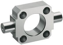
Trunnion for cover
(only for vertical Electromechanical Cylinder installation)
- Group 3, option 01
- is included in group 3 option 03
- Material: galvanized cast iron with spheroidal graphite
Trunnion for base
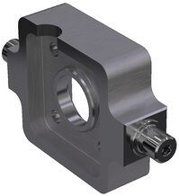
Trunnion for base
- Group 5, option 01
- is included in group 5 option 03
- Material: galvanized steel
Force sensor for EMC
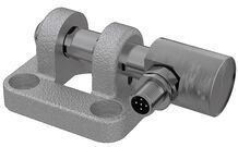
Force sensor for EMC
- For tensile and compressive forces
- Corrosion-resistant stainless steel version
- Integrated amplifier
- Low temperature coefficient
- High long term stability
Adapter
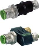
Adapter
Retaining bracket
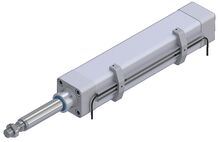
Retaining bracket
Magnetic sensors
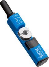
Magnetic sensors
Sensor profile
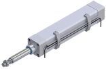
Sensor profile
Extension pieces - assembled on one side

Extension pieces - assembled on one side
Extension pieces - assembled on two sides

Extension pieces - assembled on two sides
Plug-in connector
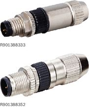
Plug-in connector
Plug screw for cover
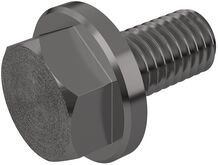
Plug screw for cover
- Material: corrosion-resistant
Port for one-point lubrication
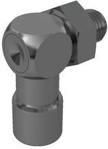
Port for one-point lubrication
- Enclosed O-ring
- FPM seals
Safety Instructions
Required and supplementary documentation
For further instructions and information, please refer to the documentation for this product.
You can find PDF files of these documents on the Internet at www.boschrexroth.com/mediadirectory.
We would also be happy to send you the documents that you want.
If you are unsure about using this product, please contact Bosch Rexroth.
Ordering codes
Order overview
| Size | Part number | Short product name | CAD data | Buy |
| 32 | R156010010 | EMC-032-NN-2 | ||
| 40 | R156020010 | EMC-040-NN-2 | ||
| 50 | R156030010 | EMC-050-NN-2 | ||
| 63 | R156040010 | EMC-063-NN-2 | ||
| 80 | R156050010 | EMC-080-NN-2 | ||
| 100 | R156060010 | EMC-100-NN-2 | ||
| 100-XC | R156070010 | EMC-100-XC-2 |
Explanation of short product name
| Electromechanical Cylinder EMC example | EMC-032-NN-2 | |
| System | EMC | Electromechanical Cylinder |
| Size | 032 | 032/040/050/063/080/100 |
| Version | NN | Normal version |
| XC | Extra Capacity | |
| Generation | 2 | Product generation 2 |
Downloads
 | Electromechanical Cylinders EMC Gen. 2 Manual | R320103102_EN | 2021-04-01 | English | PDF | 6.9MB Product Groups: Electromechanical Cylinder |
| Declaration of Incorporation for single axis Linear Motion Systems Certificate | R320103141 | 2020-06-01 | All languages | PDF | 409k Product Groups: Linear axes and electromechanical cylinders |
| Safety Instructions for Linear Motion Systems Manual | R320103152_en | 2015-01-01 | English | PDF | 593k Product Groups: Linear axes and electromechanical cylinders |
| Electromechanical Cylinder EMC Catalog | 2021-06-01 | English | PDF | 17.5MB Product Groups: Electromechanical Cylinder only PDF |









Цена по запросу
Цена по запросу
Нет отзывов об этом товаре.