
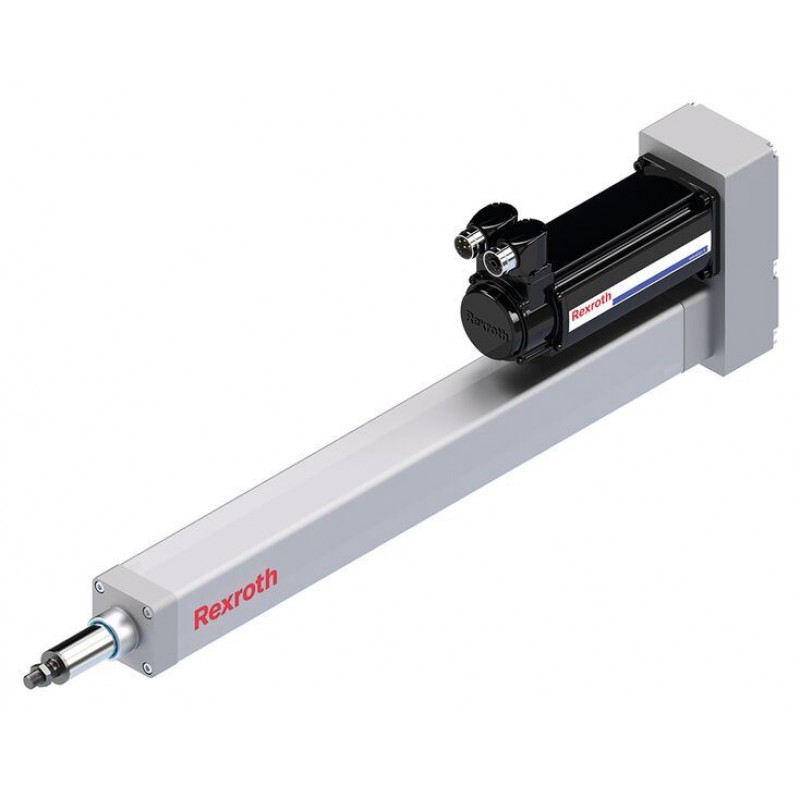
Доступно к заказу
Цена по запросу
И выбери подходящего.
Description
- High-precision ball screw assemblies: for high performance with maximum cost-effectiveness
- Complete building system with great variability: can be adapted to a wide range of applications
- Complete turn-key system: minimal construction and installation effort
- The smart, freely programmable drive system allows the realization of complex travel profiles (parameters for force, position and travel speed can be set as required over the complete working travel range).
- Optimized lubrication concept: optional connection to a one-point lubrication system reduces downtime.
Product description
Structure and attachments
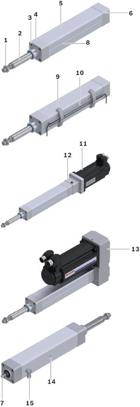
Structural design
1 Hexagon nut
2 Piston rod (stainless steel)
3 Cylinder screw (for mounting fastening element and motor attachments)
4 Cover
5 Protective profile
6 Rear end cap
7 Screw journal
8 Groove for sensor profile (opposite the lube nipple)
Attachments
9 Retaining bracket (for sensor profile)
10 Sensor profile
11 Motor
12 Mount and coupling
13 Timing belt side drive
14 Lube nipple
15 Port for pressure compensation
Motor mount and coupling
The motor mount is used to attach the motor to the EMC and as a closed housing unit for the coupling. With the coupling, the torque of the motor is transmitted free of distortive stresses to the screw journal of the EMC.
Timing belt side drive
This configuration results in the shortest possible length of the EMC.
The space-saving, closed housing serves as protection for the belt, motor bracket and to connect fastening elements.
The following gear ratios are available:
i = 1 : 1
i = 1 : 1.5
i = 1 : 2
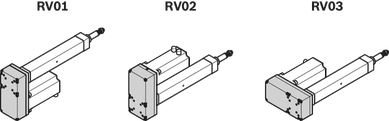
The timing belt side drive can be mounted in three directions (RV01 to RV03).
Features at a glance
The hygienic design of the EMC with smooth surfaces prevents the formation of dirt and allows for easy cleaning of the cylinder. A sensor profile can be mounted to the aluminum profile to allow the use of limit and/or reference switches outside of the aluminum profile.
The EMC is initially lubricated with standard grease or NSF-H1 grease and is therefore ready for immediate use. Alternatively, the built-in Rexroth Ball Screw Assembly can also be ordered only conserved for initial lubrication by the customer. The EMC can be connected to a central lubrication system with fluid grease. A lube fitting is included if the appropriate lubrication option has been selected.
Design of protection class IP65
Seals between the end caps and the aluminum profile and a reinforced seal on the piston rod ensure reliable protection against dust and water ingress. A connection for pressure compensation (15) in the housing prevents underpressure in the cylinder by allowing controlled air flow between interior and environment. Both the electric cylinder and the motor mountings with IP65 satisfy specifications in accordance with IEC 60 529.
Design of protection class IP65 +R (resistant)
In addition to the benefits of the IP65 rating, this version provides chemical-resistant seals between the end caps and the aluminum profile, as well as at the piston rod.
The lube fitting (14), the port for pressure compensation (15) and the hexagon nut (1) are made from stainless steel.
As additional accessories corrosion-resistant plug screws for the socket head screws in the front end cap are available.
Technical data
Note on dynamic load capacities
In relation to the desired service life, generally speaking an equivalent dynamic axial load of up to about 20 % of the dynamic load capacity (C) has proven effective.
See the section titled "Project engineering notes" and service life graphs in the section titled "Diagrams/characteristic curves".
Do not exceed the technical data.
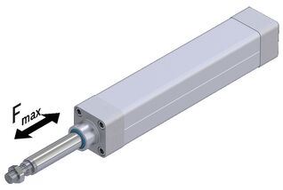
Load capacities and moments
| Size | EMC-063 | |||
| d0 x P | mm | 25 x 5 | 25 x 10 | 25 x 25 |
| C | N | 17200 | 17000 | 15900 |
| Fmax | N | 15900 | 14800 | 8000 |
General technical data
| Size | EMC-063 | |||
| d0 x P | mm | 25 x 5 | 25 x 10 | 25 x 25 |
| Lad | mm | 148 | 167 | 199 |
| smin | mm | 45 | 65 | 95 |
| smax per | mm | 1200 | ||
| mca fix | kg | 1.059 | 1.291 | 1.679 |
| mca var | kg/mm | 02 | ||
| kg fix | kg | 3.018 | 3.417 | 4.047 |
| kg var | kg/mm | 0.01 | ||
Drive data
| Size | EMC-063 | |||
| d0 x P | mm | 25 x 5 | 25 x 10 | 25 x 25 |
| Fmax | N | 15900 | 14800 | 8000 |
| Mp | Nm | 14.1 | 26.2 | 35.4 |
| vmax | m/s | 0.28 | 0.55 | 1.38 |
| mca fix | kg | 1.059 | 1.291 | 1.679 |
| mca var | kg/mm | 02 | ||
| kJ fix 1) | kg·mm² | 39.693 | 48.227 | 762 |
| kJ var 1) | kg·mm | 0.223 | 0.243 | 0.242 |
| kJ m 1) | mm² | 0.633 | 2.533 | 15.831 |
| MRs | Nm | 0.75 | 0.8 | 1 |
| amax | m/s² | 28.9 | 50 | |
| np | rpm | 3300 | ||
| Total axial clearance cylinders 2) | µm | 5 | 10 | 20 |
| 1) | Constants for calculating the mass moment of inertia. For formulas, see section "Project planning notes" |
| 2) | Total axial clearance of the EMC when new |
Effectiveness η = 0.9
Notes:
The travel range can be selected in mm steps between smin and smax perm..
Fmax and vmax depend on the selected travel range (smax) of the EMC. See section "Diagrams/characteristic curves".
Mass of EMC
Weight calculation without the motor and without motor attachment

Weight calculation without motor with timing belt side drive

Weight calculation without motor with mount and coupling

Moved mass of system

Length calculation

Drive data for motor attachment via mount and coupling
| Size | d0 x P | Motor | Mount and coupling | ||||||||
| Fmax2) | Mp2) | vmax2) | MRs | kJ fix1) | kJ var1) | kJ m1) | mc | amax | |||
| mm | N | Nm | m/s | Nm | kgmm2 | kgmm | mm2 | kg | m/s2 | ||
| EMC-063 | 25 x 5 | MSM041B MS2N05 | 15900 | 14,1 | 0,28 | 0,75 | 249,693 | 0,223 | 0,633 | 1,77 | 28,9 |
| MS2N04 | 103,693 | 1,28 | |||||||||
| MS2N06 | 249,693 | 1,97 | |||||||||
| 25 x 10 | MSM041B MS2N05 | 14800 | 26,2 | 0,55 | 0,80 | 258,227 | 0,243 | 2,533 | 1,77 | 50,0 | |
| MS2N04 | 10700 | 18,9 | 112,227 | 1,28 | |||||||
| MS2N06 | 14800 | 26,2 | 258,227 | 1,97 | |||||||
| 25 x 25 | MSM041B MS2N05 | 8000 | 35,4 | 1,38 | 1,00 | 286,002 | 0,242 | 15,831 | 1,77 | ||
| MS2N04 | 4300 | 19,0 | 140,002 | 1,28 | |||||||
| MS2N06 | 8000 | 35,4 | 286,002 | 1,97 | |||||||
| 1) | Constants for calculating the mass moment of inertia. For formulas, see section "Project planning notes" |
| 2) | Force or torque and speed can be limited by the motor |
Effectiveness η = 0.9
Note:
All data is given for the complete mechanical drive train (EMC with coupling) at the reference point motor shaft.
Fmax and vmax depend on the selected travel range (smax) of the EMC. See section "Diagrams/characteristic curves".
Actual results depend on the selected motor-controller combination.
The motor torque might need to be limited.
Drive data for motor attachment using the timing belt side drive
| Size | d0 x P | i1) | Motor | Timing belt side drive | ||||||||
| Fmax3) | Mp3) | vmax3) | MRs | kJ fix2) | kJ var2) | kJ m2) | msd | amax | ||||
| mm | N | Nm | m/s | Nm | kgmm2 | kgmm | mm2 | kg | m/s2 | |||
| EMC-063 | 25 x 5 | 1 | MSM041B | 15900 | 14,1 | 0,28 | 1,20 | 1081,2 | 0,223 | 0,633 | 4,2 | 28,9 |
| MS2N04 | 1082,9 | 4,6 | ||||||||||
| MS2N05 | 1,25 | 1350,2 | 4,5 | |||||||||
| MS2N06 | 1359,7 | 4,7 | ||||||||||
| 2 | MSM041B | 7,0 | 0,83 | 202,2 | 0,056 | 0,158 | 3,9 | |||||
| MS2N04 | 188,2 | 4,2 | ||||||||||
| MS2N05 | 0,88 | 232,0 | ||||||||||
| 25 x 10 | 1 | MSM041B | 10400 | 18,5 | 0,55 | 1,25 | 1089,7 | 0,243 | 2,533 | 50 | ||
| MS2N04 | 1091,5 | 4,6 | ||||||||||
| MS2N05 | 11400 | 20,2 | 1,30 | 1358,7 | 4,5 | |||||||
| MS2N06 | 1368,2 | 4,7 | ||||||||||
| 2 | MSM041B | 10400 | 9,3 | 0,85 | 204,3 | 0,061 | 0,633 | 3,9 | ||||
| MS2N04 | 190,4 | 4,2 | ||||||||||
| MS2N05 | 11400 | 10,1 | 0,90 | 234,1 | ||||||||
| 25 x 25 | 1 | MSM041B | 4200 | 18,6 | 1,38 | 1,45 | 1117,5 | 0,242 | 15,831 | |||
| MS2N04 | 1119,2 | 4,6 | ||||||||||
| MS2N05 | 5200 | 23,1 | 1,50 | 1386,5 | 4,5 | |||||||
| MS2N06 | 1396,0 | 4,7 | ||||||||||
| 2 | MSM041B | 4200 | 9,3 | 0,95 | 211,3 | 0,060 | 3,958 | 3,9 | ||||
| MS2N04 | 197,3 | 4,2 | ||||||||||
| MS2N05 | 5200 | 11,6 | 1,00 | 241,0 | ||||||||
| 1) | Gear ratio of the timing belt side drive. |
| 2) | Constants for calculating the mass moment of inertia. For formulas, see section "Project planning notes" |
| 3) | Force or torque and speed can be limited by the motor |
Effectiveness η = 0.9
Note:
All data is given for the complete mechanical drive train (EMC with timing belt side drive) at the motor shaft reference point.
Fmax and vmax depend on the selected travel range (smax) of the EMC. See section "Diagrams/characteristic curves".
Actual results depend on the selected motor-controller combination.
The motor torque might need to be limited.
Normal operating conditions
| Size | EMC-063 | |
| Permissible ambient temperature with Rexroth servo motor 1) | 0 °C ... +40 °C | |
| Permissible ambient temperature for mechanical system 2) | -10 °C ... +50 °C | |
| Duty cycle | % | 100 |
| Protection type | IP54, IP65 as an option | |
| Normal stroke | The distance traveled per cycle is ≥ smin (see diagram). | |
| 1) | Performance losses from 40°C |
| 2) | No passing below the dew point |
Stroke definition
Normal stroke
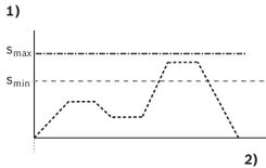
| 1) | Travel |
| 2) | Time |
Short stroke
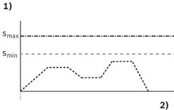
| 1) | Travel |
| 2) | Time |
short-stroke: The distance traveled per cycle is < smin (see diagram).
Short-stroke Case 1:
Distance in cycle < smin and> 2 x screw lead:
- Carry out the life expectancy calculation with 69% of the dynamic load capacity
- Halve the maintenance interval (see "Instructions EMC R320103102")
Short-stroke Case 2:
Distance in cycle < smin and ≤ 2 x screw lead:
- Only permissible with regular lubricating strokes
- Perform life expectancy calculation with reduction to the dynamic load capacity
- Adjust the maintenance interval
Please contact Bosch Rexroth for this.
Legend
| Symbol | Description | Unit |
| amax | Maximum acceleration travel | m/s2 |
| C | Dynamic load capacity, linear guide | N |
| d0 | Nominal diameter of ball screw drive | mm |
| Fmax | Max. permissible axial force EMC | N |
| i | Gear ratio | - |
| kg fix | Constant for the fixed portion of the mass | kg |
| kg var | Constant for the variable-length portion of the mass | kg/mm |
| kJ fix | Constant for fixed-length portion of mass moment of inertia | kgmm2 |
| kJ m | Constant for mass-specific portion of mass moment of inertia | mm2 |
| kJ var | Constant for variable-length portion of mass moment of inertia | kgmm |
| Lad | Additional length | mm |
| LBC | Overall length (without piston rod) | mm |
| mfc | Mass of mount and coupling | kg |
| mca | Moved mass of system | kg |
| mca fix | Constant for fixed portion of moving mass | kg |
| mca var | Constant for variable-length portion of moving mass | kg/mm |
| Mp | Max. permissible drive torque (at drive journal) | Nm |
| MRs | Frictional torque of system | Nm |
| ms | Mass of the Linear Motion System (without attachments) | kg |
| msd | Mass of timing belt side drive | kg |
| nP | Maximum permissible rotary speed of EMC | min-1 |
| P | Screw lead | mm |
| smax | Maximum travel range | mm |
| smax zul | Maximum permissible travel range | mm |
| smin | Minimum travel | mm |
| vmax | Maximum permissible speed | m/s |
| η | Efficiency | - |
Diagrams/characteristic curves
Axial load on the cylinder mechanics
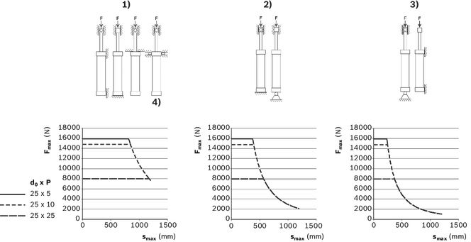
| 1) | Case I |
| 2) | Case II |
| 3) | Case III |
| 4) | only allowed vertically |
| Fmax = maximum permissible axial force (N) | |
| smax = maximum travel path (mm) |
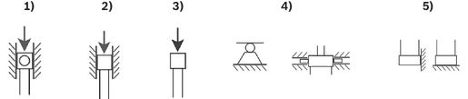
| 1) | Piston rod in swivel bearings |
| 2) | Piston rod with linear travel range |
| 3) | Piston rod free |
| 4) | Swivel mount |
| 5) | Fixed mount |
Service life
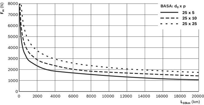
| The stated values comply with the specified relubrication intervals(see “Maintenance” chapter). | |
| For calculation of the equivalent dynamic axial load Fm see "Project planning instructions" chapter. | |
| Fm = equivalent dynamic axial load (N) | |
| L10km = nominal service life (km) |
Permissible travel speeds
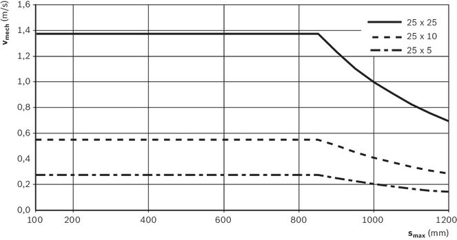
| vmech = maximum permissible speed of the mechanism (m/s) | |
| smax = maximum travel distance (mm) |
Load on the piston rod
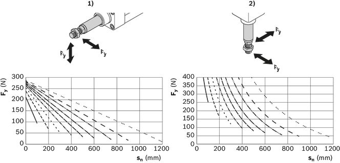
| 1) | Horizontal installation |
| 2) | Vertical mounting |
| Fy = lateral force (N) | |
| sn = position of the piston rod (mm) |
Diagrams are valid for:
- 25% of Fmax
- a speed of 0.5 m/s
Characteristics for smax
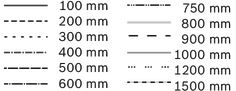
Definition smax/sn
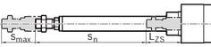
| 1) | smax = maximum travel path (mm) |
| 2) | sn = position of the piston rod (mm) |
| 3) | LZS = Retracted position of the piston rod (mm) |
Fields of application
Areas of application
Electromechanical cylinders (EMC) have many uses. Due to their specific characteristics, they offer advantages in terms of accuracy, dynamics and controllability, and can therefore not only help to shorten cycle times but also to increase flexibility and quality in the manufacturing process. Their compact design makes them ideal for use in tightly confined spaces.
Possible application areas are:
- servo presses and forming technology
- joining technology
- thermoforming
- injection molding and blow-molding machines
- woodworking machines
- assembly and handling technology
- packaging machines and conveyor systems
- food processing machines
- testing technology and laboratory applications
- special machines
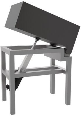
Application examples
| Joining and pressing | Transporting |
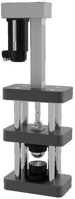 | 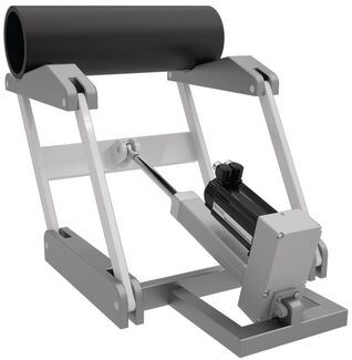 |
| Forming / thermoforming | Lifting |
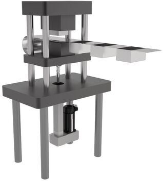 |  |
Axial load of the cylinder mechanism
Note on special installation case and application example
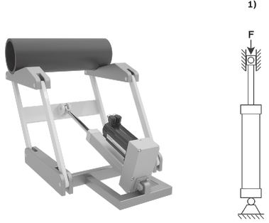
| 1) | Installation case III |
Application example:
Installation - case III: Swivel clevis mount on the timing belt side drive, piston rod guided by means of rod end bearing or fork clevis.
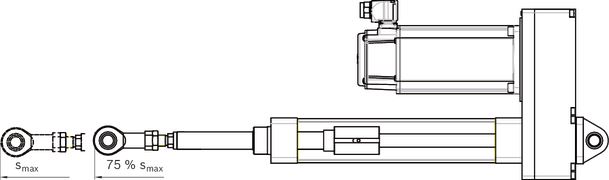
Note: In this case the cylinder mechanism of the EMC is loaded by its own weight in a horizontal position.
Thus, the piston rod may be extended horizontally only up to 75 % of smax.
Example for determining the permissible axial load of the cylinder mechanism
Pre-selection for the above installation case III as an application example:
- EMC-063 Rexroth Ball Screw Assembly 25 x 10
- selected travel distance smax 500 mm
- with timing belt side drive i = 1 for MS2N05
- Installation with clevis mount and swivel mount
Max. permissible axial load according to installation from diagram: approx. 4200 N.
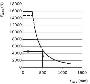
Fmax from table "Drive data" for motor mounting via timing belt side drive:
Fmax = 11400 N
The actual achievable axial force of the system also depends on the selected motor / controller combination (see section on "Project engineering notes").
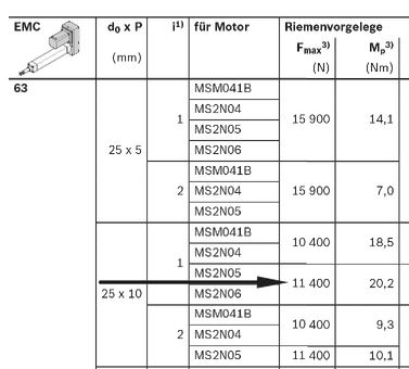
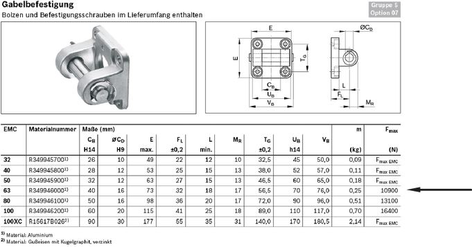
Note: Limitations caused by fastening elements that can be ordered are not taken into account in the consideration of the drive train.
Applies to clevis mount size 63 e.g. Fmax 10900 N.
For Fmax the smallest value is 4200 N.
Dimensions
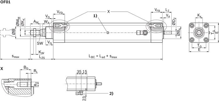
| 1) | Funnel-type lube nipple DIN 3405-A M6 |
| 2) | Connection for pressure compensation hose ⌀ 8 mm, thread in housing M10x1 (only with IP65/IP65R, option housing 02/03) |
Dimensions
| Size | EMC-063 | ||||
| d0 x P | 25 x 5 | 25 x 10 | 25 x 25 | ||
| Lad | mm | 148 | 167 | 199 | |
| AM | mm | 32 | |||
| Tolerance for AM | mm | - 0.1 | |||
| B | d11 | mm | 45 | ||
| BA | h7 | mm | 45 | ||
| DZ | h7 | mm | 15 | ||
| E | mm | 75 | |||
| Tolerance for E | mm | ± 0.1 | |||
| KK | M16x1,5 | ||||
| KW | mm | 8 | |||
| Kx | mm | 24 | |||
| LZS | mm | 76.5 | |||
| LZ | mm | 35 | |||
| MM | f8 | mm | 30 | ||
| RT | M8 | ||||
| BG | mm | 18 | |||
| RL | mm | 5 | |||
| SW | mm | 17 | |||
| TG | mm | 56.5 | |||
| VA | mm | 4 | |||
| Tolerance for VA | mm | ± 0.1 | |||
| VD | mm | 5 | |||
| VFB | mm | 40 | |||
| VFD | mm | 38 | |||
| VG | mm | 25 | |||
| Tolerance for VG | mm | ± 0.1 | |||
| WA | mm | 8 | |||
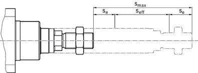
Effective stroke
The overflow must be greater than the braking distance. The acceleration travel can be adopted as the guideline value for the braking distance.

Length calculation:
Total length of EMC for motor attachment with mount and coupling =

Total length of EMC for motor attachment with timing belt side drive =

(Lf, Lm and G see section on "Mounting the motor")
Legend
| Symbol | Description | Unit |
| se | Excess travel | mm |
| seff | Effective stroke | mm |
| smax | Maximum travel range | mm |
Project planning information
Calculation
Mounting
Mounting
Commissioning
Parameterization (start-up)
The nameplate contains reference information on the production of the linear motion system as well as technical start-up parameters.
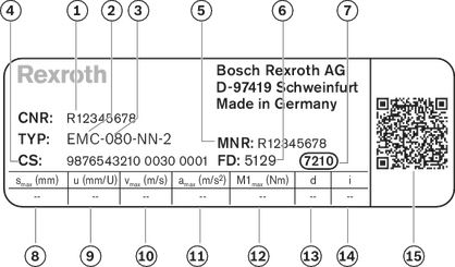
| Position | Symbol | Description |
| 1 | CNR | Customer's part number |
| 2 | TYP | Short product name |
| 3 | 080 | Size |
| 4 | CS | Customer information |
| 5 | MNR | Part number |
| 6 | FD | Manufacturing date |
| 7 | 7210 | Manufacturing location |
| 8 | smax | Maximum travel range |
| 9 | u | Lead constant without motor attachment |
| 10 | vmax | Maximum speed |
| 11 | amax | Maximum acceleration travel |
| 12 | M1max | Maximum drive torque at motor journal |
| 13 | d | Direction of motor rotation to move in positive (+) direction CW = clockwise CCW = counter clockwise |
| 14 | i | Gear ratio |
| 15 | QR code |
Note
The values given describe the mechanical limit values of the axle.
Limits for the supplied fastening elements and application-related installation cases are not taken into account here.
Maintenance
Lubrication and maintenance
Accessories
Synchronous servo motor
MSM041
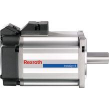
Synchronous servo motor
MSM041
- Maximum torque Mmax 7.1 Nm
- Maximum speed nmax 4500 rpm
- Multi-turn absolute encoder
- Highly dynamic
- High power density
Synchronous servo motor with self-cooling
MS2N04
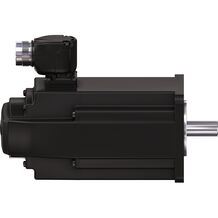
Synchronous servo motor with self-cooling
MS2N04
- Maximum torque Mmax 19.7 Nm
- Maximum speed nmax 6000 rpm
Synchronous servo motor with self-cooling
MS2N05
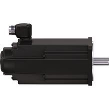
Synchronous servo motor with self-cooling
MS2N05
- Maximum torque Mmax 34 Nm
- Maximum speed nmax 6000 rpm
Synchronous servo motor with self-cooling
MS2N06
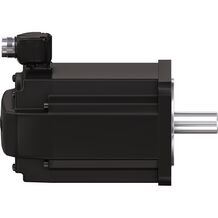
Synchronous servo motor with self-cooling
MS2N06
- Maximum torque Mmax 53.4 Nm
- Maximum speed nmax 6000 rpm
Flexible coupling
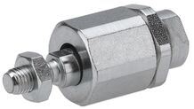
Flexible coupling
- Group 2, option 04
- Material: galvanized steel
- radial clearance 0 ... 2 mm
Flexible coupling with mounting plate
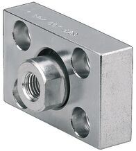
Flexible coupling with mounting plate
- Group 2, option 03
- Material: galvanized steel
Flange mounting
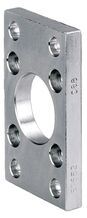
Flange mounting
- Group 3, option 04
- Material: galvanized steel
Foot mounting for mounting on the cover or timing belt side drive
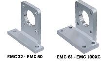
Foot mounting for mounting on the cover or timing belt side drive
- Group 3, option 06/group 5, option 06
- Material: galvanized steel
Foot mounting with centering ring for foot mounting
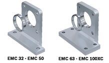
Foot mounting with centering ring for foot mounting
- Group 5, option 05
- Material: galvanized steel
Clevis mount with force measuring bolts
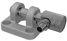
Clevis mount with force measuring bolts
- Group 1, option 02; group 5, option 10
- Material: Aluminum / galvanized spheroidal graphite iron
Clevis mount on the timing belt side drive
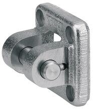
Clevis mount on the timing belt side drive
- Group 1, option 01; group 5, option 08
- Material: Aluminum / galvanized spheroidal graphite iron
Clevis mount
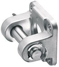
Clevis mount
- Group 5, option 07
- Material: Aluminum / galvanized cast iron with spheroidal graphite cast iron
Fork clevis with internal thread
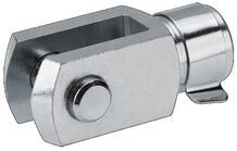
Fork clevis with internal thread
- Group 2, option 02
- Material: galvanized steel
Female spherical rod end bearing, galvanized steel
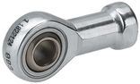
Female spherical rod end bearing, galvanized steel
- Group 2, option 01
- Material: galvanized steel
Female spherical rod end bearing, stainless steel
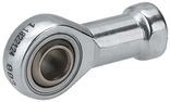
Female spherical rod end bearing, stainless steel
- Group 2, option 07
- Material: Stainless steel
Swivel mount for force measuring bolt
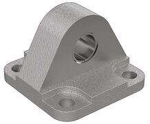
Swivel mount for force measuring bolt
- Group 6, option 05
- Material: Aluminum
Swivel bearing
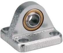
Swivel bearing
- Group 6, option 04
- Material: Aluminum / galvanized cast iron with spheroidal graphite cast iron
Swivel bearing, high
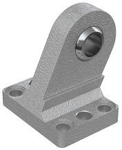
Swivel bearing, high
- Group 6, option 03
- Material: galvanized cast iron with spheroidal graphite
Bearing for trunnion
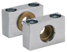
Bearing for trunnion
- are included in group 3, option 03, group 5, option 03
- Material: galvanized steel, with sockets made from sintered bronze
Bearing block
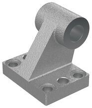
Bearing block
- Group 6, option 01
- Material: galvanized cast iron with spheroidal graphite
Nut, galvanized steel
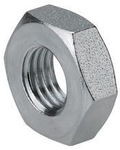
Nut, galvanized steel
- Group 2, option 05
- Material: galvanized steel
Nut, stainless steel
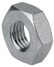
Nut, stainless steel
- Group 2, option 06
- Material: Stainless steel
Swivel flange
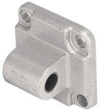
Swivel flange
- Group 6, option 02
- Material: Aluminum / galvanized cast iron with spheroidal graphite cast iron
Trunnion for cover
(only for vertical Electromechanical Cylinder installation)
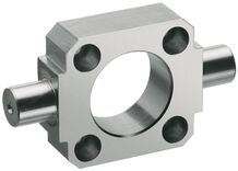
Trunnion for cover
(only for vertical Electromechanical Cylinder installation)
- Group 3, option 01
- is included in group 3 option 03
- Material: galvanized cast iron with spheroidal graphite
Trunnion for base
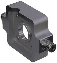
Trunnion for base
- Group 5, option 01
- is included in group 5 option 03
- Material: galvanized steel
Force sensor for EMC
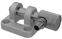
Force sensor for EMC
- For tensile and compressive forces
- Corrosion-resistant stainless steel version
- Integrated amplifier
- Low temperature coefficient
- High long term stability
Adapter
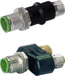
Adapter
Retaining bracket
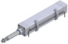
Retaining bracket
Magnetic sensors
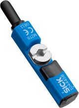
Magnetic sensors
Sensor profile
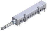
Sensor profile
Extension pieces - assembled on one side

Extension pieces - assembled on one side
Extension pieces - assembled on two sides

Extension pieces - assembled on two sides
Plug-in connector
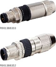
Plug-in connector
Plug screw for cover
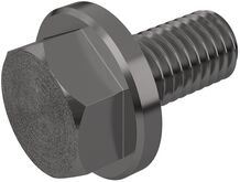
Plug screw for cover
- Material: corrosion-resistant
Port for one-point lubrication
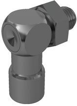
Port for one-point lubrication
- Enclosed O-ring
- FPM seals
Safety Instructions
Required and supplementary documentation
For further instructions and information, please refer to the documentation for this product.
You can find PDF files of these documents on the Internet at www.boschrexroth.com/mediadirectory.
We would also be happy to send you the documents that you want.
If you are unsure about using this product, please contact Bosch Rexroth.
Motor attachment
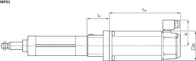
Dimension drawing for motor attachment with mount and coupling
Dimension drawing motor attachment with timing belt side drive
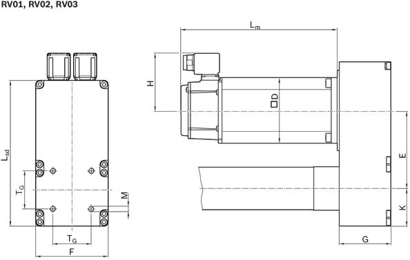
Dimensions
| Size | Motor | i | E | K | G | ▢D | H | Lm | Lsd | Lf | F | TG | M | Max. permissible screw-in depth1) | |
| without brake | With brake | ||||||||||||||
| mm | mm | mm | mm | mm | mm | mm | mm | mm | mm | mm |
| mm | |||
| EMC-063 | MSM041B | 1 | 117,2 | 56,0 | 77,0 | 80 | 53,0 | 112,0 | 149,0 | 245 | 95 | 116,0 | 56,5 | M8 | 16,0 |
| 2 | 116,2 | ||||||||||||||
| MS2N03 | 1 | 117,2 | 82 | 83,5 | 185,5 | 215,5 | 88 | ||||||||
| 2 | 116,2 | ||||||||||||||
| MS2N05 | 1 | 117,2 | 98 | 85,5 | 203,0 | 233,0 | 95 | ||||||||
| 2 | 116,2 | ||||||||||||||
| MS2N06 | 1 | 117,2 | 116 | 98,5 | 226,0 | 259,0 | |||||||||
| 1) | Do not exceed max. permissible screw-in depth for threads «M» |
Measurement and test reports
Documentation
Standard report, option 01
The standard report serves to confirm that the checks listed in the report have been carried out and that the measured values lie within the permissible tolerances.
Checks listed in the standard report:
- Functional check of mechanical components
- Functional check of electrical components
- Design is in accordance with order confirmation
Frictional torque measurement of the complete system, option 02
All services according to standard report.
The frictional torque M is measured over the entire travel range.
Example diagram
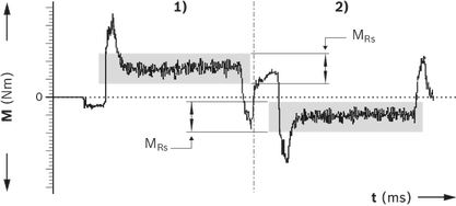
| 1) | Advance |
| 2) | Return |
| MRS = frictional torque (N) | |
| t = travel time (ms) |
Lead deviation of the Screw Drive, option 03
All services according to standard report.
In addition to the graphical illustration (see figure), a measurement report is supplied in tabular form.
Example diagram
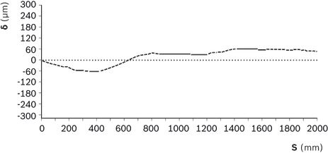
| δ = deviation (μm) | |
| s = measured travel (mm) | |
Ordering codes
Order overview
| Size | Short product name | Configuration and ordering |
| EMC-063 | EMC-063-NN-2 | Configurator |
Explanation of short product name
| Electromechanical Cylinder EMC example | EMC-032-NN-2 | |
| System | EMC | Electromechanical Cylinder |
| Size | 032 | 032/040/050/063/080/100 |
| Version | NN | Normal version |
| XC | Extra Capacity | |
| Generation | 2 | Product generation 2 |
Configuration and ordering
Configuration and ordering – Fastening elements
General ordering example – Electromechanical Cylinder EMC
Downloads
 | Electromechanical Cylinders EMC Gen. 2 Manual | R320103102_EN | 2021-04-01 | English | PDF | 6.9MB Product Groups: Electromechanical Cylinder |
| Declaration of Incorporation for single axis Linear Motion Systems Certificate | R320103141 | 2020-06-01 | All languages | PDF | 409k Product Groups: Linear axes and electromechanical cylinders |
| Safety Instructions for Linear Motion Systems Manual | R320103152_en | 2015-01-01 | English | PDF | 593k Product Groups: Linear axes and electromechanical cylinders |
| Electromechanical Cylinder EMC Catalog | 2021-06-01 | English | PDF | 17.5MB Product Groups: Electromechanical Cylinder only PDF |



Нет отзывов об этом товаре.