
Доступно к заказу
Цена по запросу
И выбери подходящего.
Description
- Four different lube versions
- Pre-tensioned toothed belt
- Intelligent toothed belt guide protects inner components
- Realization of greater lengths of up to 10000 mm
- Repeatability of up to ± 0.05 mm
Product description
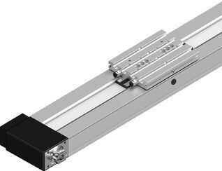
Compact Modules with Ball Rail Systems and belt drive are characterized by their high power density due to their compact dimensions. Externally, the Compact Modules can be recognized by their relatively flat construction. The width to height ratio of all types is around 2:1.
Structure and attachments

Motor attachment – direct attachment with i = 1
The motor is attached directly to the compact module’s drive end enclosure via a motor mount.

Motor attachment – with gear
The planetary gearbox is attached by a mount. The mount serves to fasten the gearbox to the CRK and as a closed housing. Due to the connection without coupling, the drive torque is transferred to the drive shaft of the Compact Module with minimal torsional deflection. Available gear ratios: i = 3 (for CKR-145 and CKR-200), i = 5, i = 10

Structural design
1 Drive end enclosure
2 Frame
3 Belt drive
4 Carriage
5 Non-drive end enclosure
Additional components
6 Magnetic sensor
7 Mounting duct
8 Socket/plug
9 Connection plate
10 Flanged type
11 Planetary gearbox
12 Motor
Lubrication versions
Lube version LSS, LPG
- Grease lubrication with manual grease gun via frame, carriage or via connection plate

| 1) | Connection plates |
Lube version LCF, LCO
- 2 lube connections
- Prepared for connection to central lubrication systems
Notes:
LSS:
- Initial lubrication by Bosch Rexroth
- Relubrication using manual grease gun
LPG:
- Ball Rail System and Ball Screw Assembly only with corrosion prevention
- Relubrication using manual grease gun
- Basic lubrication required
LCF:
- Prepared for connection to central lubrication systems for liquid grease (NLGI grade 00 in accordance with DIN 51818)
- • Lubrication with liquid grease only via single-line piston distributor system
- Basic lubrication required
LCO:
- Prepared for connection to central lubrication systems for oil
- Oil lubrication only via single-line piston distributor system
- Runner Block and Ball Screw Assembly nut with integrated non-return valves
- Basic lubrication required
Technical data

| 1) | Applicable to CKK-110, -145, -200 with Resist cover |
Maximum values for each size
| Size | CKR-070 | CKR-090 | CKR-110 | CKR-145 | CKR-200 | |
| C | N | 3830 | 7505 | 32035 | 76025 | 121185 |
| Mt | Nm | 77 | 203 | 1057 | 3345 | 7877 |
| ML | Nm | 94 | 244 | 1361 | 3801 | 10604 |
| Mx max | Nm | 77 | 203 | 396 | 1267 | 2750 |
| My max | Nm | 94 | 244 | 510 | 1440 | 3701 |
| Mz max | Nm | 51 | 132 | 240 | 683 | 1744 |
| Fy max | N | 2070 | 4050 | 5650 | 13660 | 19925 |
| Fz1 max | N | 3830 | 7505 | 12000 | 28800 | 42300 |
| Fz2 max | N | 3830 | 7505 | 12000 | 28800 | 42300 |
| Lmax | mm | 1500 | 5500 | 10000 | ||
| amax | m/s² | 50 | ||||
| vmax | m/s | 3 | 5 | |||
| Maximum values depends on the selected configuration. |
Legend
| Symbol | Description | Unit |
| C | Dynamic load capacity, linear guide | N |
| Mt | Dynamic torsional moment load capacity | Nm |
| ML | Dynamic longitudinal moment load capacity | Nm |
| Mx max | Maximum admissible torsional moment around the x-axis | Nm |
| My max | Maximum admissible torsional moment around the y-axis | Nm |
| Mz max | Maximum admissible torsional moment around the z-axis | Nm |
| Fy max | Maximum dynamic load in y-direction | N |
| Fz1 max | Maximum dynamic load in z-direction | N |
| Fz2 max | Maximum dynamic load in z-direction | N |
| Lmax | Maximum length | mm |
| amax | Maximum acceleration travel | m/s2 |
| vmax | Maximum permissible speed | m/s |
Dimensions

Dimensions
| Size | CKR-070 | CKR-090 | CKR-110 | CKR-145 | CKR-200 | |
| A | mm | 70 | 90 | 110 | 145 | 200 |
| H | mm | 32 | 40 | 50 | 65 | 100 |
| H1 | mm | 44.5 | 56 | 66 | 85 | 127 |
Mounting
Magnetic sensor with free cable end
1 Socket and plug
2 Sensor
3 Mounting duct
Alternatively, the sensor can also be attached by switch mounting plate and cable holder.
See the magnetic sensor with plug.

| 1) | Set screw for retention |
| 2) | Active surface |
Additional component/actuation
A mounting duct is needed to fasten the sensors and cable guides. This is suspended at the side in a slot at the Compact Module and secured with set screws (4).
The set screws are included.
The sensors are pushed into the upper T-slot (CKK/CKR-090,-110 and CKK-145) or into the lower T-slot (CKR-145, CKK/CKR-200) of the mounting duct and secured with set screws.
Switch activation is done by magnets in the carriage.

Socket - plug
Notes:
Socket and plug are not wired.
This allows optimal assignment of switching positions during start-up.
One plug is included.
The plug can be installed in three directions.
For further information, see the "Socket - plug” view.

CKK/CKR-200

Magnetic sensor with plug
1 Sensor
2 Switch mounting plate including set screws (loose) and square nut 2a
3 Cable holder including set screw (loose)

Attachment/Actuation
A switch mounting plate (2) is required to attach the sensors. This is suspended in the upper slot on the Compact Module and secured with set screws (4).
The sensors are pushed into the respective slot on the switch mounting plate and secured with one set screw.
The square nut with set screw (2a) serves as a fixed stop for the sensor (switching position when changing sensors). Parts are included in the scope of delivery of the sensor mounting kit.
Switch activation is done by magnets in the carriage.

Overview
Inductive sensors and mechanical switches for CKK/CKR-200
1 Socket and plug
2 Mechanical switch (with attachments)
3 Inductive sensor (with attachments)
4 Switching cam (attachment only at the connection plate)
5 Cable duct
Alternatively, the connection line of the switches can also be attached by cable holder.

Attachment/actuation
The switches are suspended in the upper slot on the Compact Module and secured with set screws (6).
The actuation is done using switching cams (4). This is attached with the screws to the connection plate. Fastening screws are included.

Cable duct
- The additional component is done in the lateral slots of the frame. Fastening screws widen the profile and give the cable duct a secure hold.
The cable duct will accommodate up to two cables for mechanical switches and three cables for proximity switches.
Fastening screws are included.

Accessories
Combination examples

| 1) | End of range (‒) |
| 2) | Reference |
| 3) | End of range (+) |
| 4) | Sensors with plug |
| 5) | Sensors with free cable end |
| 6) | Plug |
| 7) | Sensor extensions |
| 8) | Performance specification: suitable for flexing installation, torsion-resistant, weld spark-resistant |
| 9) | Plug |
| 10) | Adapter |

| 1) | End of range (‒) |
| 2) | Reference |
| 3) | End of range (+) |
| 4) | Screw plug |
| 5) | Sensors with plug |
| 6) | Sensors with free cable end |
| 7) | Sensors with plug |
| 8) | Plug |
| 9) | Passive distributor |
| 10) | Holding plate |
| 11) | Passive distributor |
| 12) | Extensions for passive distributors |
| 13) | Performance specification: suitable for flexing installation, torsion-resistant, weld spark-resistant |
| 14) | Higher-level control system |
Clamping fixtures for Compact Modules

Clamping fixtures for Compact Modules
Sliding blocks and springs for Compact Modules

Sliding blocks and springs for Compact Modules
Strips for Compact Modules

Strips for Compact Modules
Centering rings for Compact Modules

Centering rings for Compact Modules
Covers for Compact Modules

Covers for Compact Modules
Connection plate for CKR-070

Connection plate for CKR-070
Connection plates for CKR 090 … 200, R0375...16

Connection plates for CKR 090 … 200, R0375...16
Connection plates for CKR 090 … 200, R0375...11

Connection plates for CKR 090 … 200, R0375...11
Connecting shafts for CKR-070

Connecting shafts for CKR-070
Connecting shafts for CKR 090 … 200

Connecting shafts for CKR 090 … 200
Magnetic sensor with free line end

Magnetic sensor with free line end
Magnetic sensor with M8x1 plug

Magnetic sensor with M8x1 plug
Proximity sensor with free line end

Proximity sensor with free line end
Proximity sensor with M8x1 plug

Proximity sensor with M8x1 plug
Additional components for inductive sensor

Additional components for inductive sensor
Mechanical switch

Mechanical switch
Mechanical switch with M8x1 plug

Mechanical switch with M8x1 plug
Additional components for mechanical switch

Additional components for mechanical switch
Extension pieces - assembled on one side

Extension pieces - assembled on one side
Extension pieces - assembled on two sides

Extension pieces - assembled on two sides
Plug-in connector

Plug-in connector
Adapter

Adapter
Passive distributors

Passive distributors
Holding clip

Holding clip
Plug screw

Plug screw
Extension pieces

Extension pieces
Socket and plug
R117560102

Socket and plug
R117560102
Socket and plug
R037540000

Socket and plug
R037540000
Socket and plug
R117500153

Socket and plug
R117500153
Mounting duct

Mounting duct
Switching angle

Switching angle
Switch mounting plate

Switch mounting plate
Cable holder

Cable holder
Safety Instructions
Required and supplementary documentation
For further instructions and information, please refer to the documentation for this product.
You can find PDF files of these documents on the Internet at www.boschrexroth.com/mediadirectory.
We would also be happy to send you the documents that you want.
If you are unsure about using this product, please contact Bosch Rexroth.
Downloads
| Declaration of Incorporation for single axis Linear Motion Systems Certificate | R320103141 | 2020-06-01 | All languages | PDF | 409k Product Groups: Linear axes and electromechanical cylinders | |
| Safety Instructions for Linear Motion Systems Manual | R320103152_en | 2015-01-01 | English | PDF | 593k Product Groups: Linear axes and electromechanical cylinders | |
| Compact Modules CKK, CKR Catalog | R999000499 | 2022-02-01 | English | PDF | 24.8MB Product Groups: Compact Modules Compact Modules CKK, CKR |
Нет отзывов об этом товаре.