
Доступно к заказу
Цена по запросу
И выбери подходящего.
Description
Product description
Structural design and attachments

Structural design
1 Threaded bolt (galvanized steel)
2 Lock nut (galvanized steel)
3 Piston rod (stainless steel)
4 Thread (for mounting fastening elements)
5 Cover (aluminum, anodized)
6 Housing (aluminum, anodized)
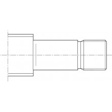
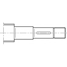
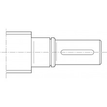
7 Screw journal
8 Base (aluminum, anodized)
9 Lube connection (on two sides)
10 Cover for T-slot for switches
11 Service openings
Attachments
12 Motor
13 Gear (optional)
14 Flange (aluminum, anodized)
15 Belt side drive (aluminum, anodized)
Motor flange and coupling
The motor flange is used to fasten the motor to the EMC and as a closed housing unit for the coupling. With the coupling, the drive torque of the motor is transmitted free of distortive stresses on the screw journal of the EMC.
Belt side drive
This configuration results in the shortest overall length of the EMC possible.
The space-saving, closed housing serves as protection for the belt, motor bracket and to connect fastening elements.
Gear ratio i = 1 : 1.5
Mounting examples

Technical data
Note on dynamic load rating
In relation to the desired service life, an equivalent dynamic axial load of up to about 20 % of the dynamic load rating (C) has generally proven effective.
Do not exceed the technical data.

Load capacities and moments
| Size | EMC-130-HP | ||
| Drive | PLSA | ||
| d0 x P | mm | 39 x 5 | 39 x 10 |
| C | N | 120000 | |
| Fmax | N | 65000 | 70000 |
General technical data
| Size | EMC-130-HP | |||
| Drive | PLSA | |||
| d0 x P | mm | 39 x 5 | 39 x 10 | |
| Lad | without trunnion | mm | 364 | |
| Lad | with trunnion | mm | 420 | |
| smin | mm | 110 | ||
| smax perm | mm | 1500 | ||
| mca fix | kg | 5.8 | ||
| mca var | kg/mm | 068 | ||
| kg fix | kg | 17 | ||
| kg var | kg/mm | 0.026 | ||
Drive data
| Size | EMC-130-HP | ||
| Drive | PLSA | ||
| d0 x P | mm | 39 x 5 | 39 x 10 |
| Fmax | N | 65000 | 70000 |
| Mp | Nm | 60.7 | 133.3 |
| vmax | m/s | 0.32 | 0.64 |
| mca fix | kg | 5.8 | |
| mca var | kg/mm | 068 | |
| kJ fix | kg·mm² | 1947 | 1958 |
| kJ var | kg·mm | 1.768 | 1.781 |
| kJ m | mm² | 0.633 | 2.533 |
| MRs | Nm | 7 | |
| amax | m/s² | 30 | |
| np | rpm | 3850 | |
| η | 0.8 | ||
Mass of the EMC-HP
Weight calculation without motor and without motor attachment*)

Moved mass of system*)

*) When calculating the mass of the entire system, the masses of the attachments/fastening elements must also be taken into account.
The indicated values apply in case of compliance with the specified relubrication intervals and to standard operation.
For short stroke operation (stroke < smin), reduction factors must be taken into consideration.
(see "Normal operating conditions" table and "Stroke definition" section).
For more calculations see configurators, and tools can be found here
Load on the piston rod
| Horizontal installation | Vertical mounting |
 |  |
| Loading the piston rod with transverse forces is not permissible | |
Normal operating conditions
| Size | EMC-130-HP | ||
| Drive | PLSA | ||
| d0 x P | mm | 39 x 5 | 39 x 10 |
| Permissible ambient temperature, cylinder with Rexroth servo motor 1) | 0 °C ... 40 °C | ||
| Permissible ambient temperature for cylinder mechanics 2) | -10 °C ... +50 °C | ||
| Permissible ambient temperature for cylinder mechanics with PLSA and low-temperature grease 3) | -30°C ... +50°C | ||
| Duty cycle 4) | % | 100 | |
| Protection type | IP 54; housing IP 65 | ||
| Normal stroke | The distance traveled per cycle is ≥ smin (see diagram). | ||
| 1) | Performance losses from 40°C |
| 2) | Up to +70 °C with low duty cycle and power |
| 3) | Up to +60 °C with low duty cycle and power |
| 4) | Depending on power required, the permissible duty cycle may be limited due to heat generation. |
Stroke definition
Normal stroke

| 1) | Travel |
| 2) | Time |
Short stroke

| 1) | Travel |
| 2) | Time |
Short stroke: The distance traveled per cycle is < smin (see diagram).
Attention:
- Short-stroke operation only permissible with regular lubricating strokes (larger smin)
- Perform life expectancy calculation with reduction to the dynamic load capacity
- Adjust the maintenance interval
Please contact Bosch Rexroth for this.
Legend
| Symbol | Description | Unit |
| amax | Maximum permissible acceleration | m/s2 |
| C | Dynamic load capacity | N |
| d0 | Diameter of Screw Drive | mm |
| Fmax | Maximum permissible axial force | N |
| kg fix | Constant for the fixed portion of the mass | kg |
| kg var | Constant for the variable-length portion of the mass | kg/mm |
| kJ fix | Constant for fixed-length portion of mass moment of inertia | kgmm2 |
| kJ m | Constant for mass-specific portion of mass moment of inertia | mm2 |
| kJ var | Constant for variable-length portion of mass moment of inertia | kgmm |
| Lad | Additional length | mm |
| mca | Moved mass of system | kg |
| mca fix | Constant for fixed portion of moving mass | kg |
| mca var | Constant for variable-length portion of moving mass | kg/mm |
| Mp | Maximum permissible drive torque | Nm |
| MRs | EMC-HP friction torque | Nm |
| ms | EMC-HP mass | kg |
| nP | Maximum permissible rotary speed of the EMC-HP | min-1 |
| P | Screw Drive lead | mm |
| PLSA | Planetary screw assembly | - |
| smax | Maximum travel range | mm |
| smax perm | Maximum permissible travel range | mm |
| smin | Minimum travel | mm |
| vmax | Maximum permissible speed | m/s |
| η | Efficiency | - |
Diagrams/characteristic curves
Service life

| Fm = Equivalent dynamic axial load (N) | |
| L10 = Nominal service life (km) | |
Travel speeds

| vmech = maximum permissible speed of the mechanism (m/s) | |
| smax = maximum travel distance (mm) |
Axial load on the cylinder mechanics

| 1) | Case I |
| 2) | Case II |
| 3) | Case III |
| 4) | only allowed vertically |
| Fmax = maximum permissible axial force (N) | |
| smax = maximum travel path (mm) |
Installation case III

Notice: In this installation case the cylinder mechanism of the EMC is loaded by its dead weight in a horizontal position. Thus, the piston rod may be extended horizontally only up to 75 % of smax.
Fields of application
Application areas
Electromechanical cylinders EMC-HP can be used in many application areas. Due to their specific characteristics, they offer advantages in terms of accuracy, dynamics and controllability, and can therefore not only help to shorten cycle times but also to increase flexibility and quality in the manufacturing process. Their space-saving design makes them ideal for use in tightly confined spaces.
Possible application areas are:
- Servo presses and forming technology
- Joining technology
- Thermoforming
- Injection molding and blow molding machines
- Woodworking machines
- Machine tools
- Assembly and handling technology
- Packaging machines and conveyor systems
- Testing equipment and laboratory applications
- Simulators
- Special machines
Application examples: Bending, lifting, pressing, transporting, etc.

Dimensions
Electromechanical Cylinder

| 1) | Funnel-type lube nipple (on two sides) DIN 3405-A M6 |
Dimensions
| Size | EMC-130-HP | |||
| Drive | PLSA | |||
| d0 x P | mm | 39 x 5 | 39 x 10 | |
| AM | mm | 71 | ||
| E | mm | 130 | ||
| J | mm | 138 | ||
| J1 | mm | 132 | ||
| KW | mm | 26 | ||
| KX | mm | 50 | ||
| LZ | mm | 78 | ||
| LZS | mm | 155 | ||
| LR | mm | 70.5 | ||
| SW | mm | 50 | ||
| TG | mm | 100 | ||
| VA | mm | 4 | ||
| VFB | without trunnion | mm | 117.5 | |
| with trunnion | mm | 173.5 | ||
| VFD | mm | 95.5 | ||
| VG | mm | 30 | ||
| ØB | mm | 95 | ||
| ØBA | mm | 80 | ||
| ⌀DZ | h7 | mm | 35 | |
| ⌀MM | f8 | mm | 60 | |
| ØKK | M33X2 | |||
Length calculation

Notice:
The presentations are schematic. Detailed contours can be found in the CAD model.
Commissioning
Parameterization (start-up)
The nameplate contains reference information on the production of the linear motion system as well as technical start-up parameters.

| Position | Symbol | Description |
| 1 | CNR | Customer's part number |
| 2 | TYP | Short product name |
| 3 | 115 | Size |
| 4 | CS | Customer information |
| 5 | MNR | Part number |
| 6 | FD | Manufacturing date |
| 7 | 7210 | Manufacturing location |
| 8 | smax | Maximum travel range |
| 9 | u | Lead constant without motor attachment |
| 10 | vmax | Maximum speed |
| 11 | amax | Maximum acceleration travel |
| 12 | M1max | Maximum drive torque at motor journal |
| 13 | d | Direction of motor rotation to move in positive (+) direction CW = clockwise CCW = counter clockwise  |
| 14 | i | Gear ratio |
| 15 | QR code (for start-up) |
Note
The values given describe the mechanical limit values of the axle.
Limits for the supplied fastening elements and application-related installation cases are not taken into account here.
Accessories
Synchronous servo motor with self-cooling
MS2N07

Synchronous servo motor with self-cooling
MS2N07
- Maximum torque Mmax 140 Nm
- Maximum speed nmax 6000 rpm
Synchronous servo motor with self-cooling
MS2N10

Synchronous servo motor with self-cooling
MS2N10
- Maximum torque Mmax 360 Nm
- Maximum speed nmax 6000 rpm
Delivery notes
Condition as delivered
The electromechanical cylinder EMC-HP is delivered as a completely assembled unit. The only parts not pre-assembled are pillow blocks, clevis brackets and the switches.
Motor attachment
Flange coupling

| 1) | Dimensions see Accessories chapter |
Gearbox

| 1) | Dimensions see Accessories chapter |
| EMC-HP | Motor | Lf | Lge | Dge | J | |
| MS2N07 | MS2N10 | Gearbox | Motor | |||
| MS2N10 | ||||||
| mm | mm | mm | mm | mm | mm | |
| 130 | 154 | 179 | – | – | – | 138 |
Timing belt side drive

| 1) | Dimensions see Accessories chapter |
| EMC-HP | E | F | G | Motor | G1 | J | K | Lsd | Lge | Dge |
| Gearbox | Motor | |||||||||
| MS2N10 | ||||||||||
| mm | mm | mm | mm | mm | mm | mm | mm | mm | mm | |
| 130 | 211 | 200 | 91 | 87 | – | 137 | 100 | 458 | – | – |
Measurement and test reports
Documentation
Standard report, option 01
The standard report serves to confirm that the checks listed in the report have been carried out and that the measured values lie within the permissible tolerances.
Checks listed in the standard report:
- Functional check of mechanical components
- Functional check of electrical components
- Design is in accordance with order confirmation
Frictional torque measurement of the complete system, option 02
All services according to standard report.
The frictional torque M is measured over the entire travel range.
Example diagram

| 1) | Advance |
| 2) | Return |
| MRS = frictional torque (N) | |
| t = travel time (ms) |
Lead deviation of the Screw Drive, option 03
All services according to standard report.
In addition to the graphical illustration (see figure), a measurement report is supplied in tabular form.
Example diagram

| δ = deviation (μm) | |
| s = measured travel (mm) | |
Ordering codes
Order overview
| Size | Short product name | Configuration and ordering |
| EMC-130-HP | EMC-130-HP-1 | Configurator |
Explanation of short product name
| Example for electromechanical cylinder EMC-HP | EMC-130-HP-1 | |
| System | EMC | ElectroMechanical Cylinder |
| Size | 130 | 115/130/160 |
| Version | HP | High Power |
| Generation | 1 | Product generation 1 |
Downloads
| Declaration of Incorporation for single axis Linear Motion Systems Certificate | R320103141 | 2020-06-01 | All languages | PDF | 409k Product Groups: Linear axes and electromechanical cylinders | |
| Safety Instructions for Linear Motion Systems Manual | R320103152_en | 2015-01-01 | English | PDF | 593k Product Groups: Linear axes and electromechanical cylinders | |
| Electromechanical cylinder EMC-HP Manual | R320103219 | 2021-11-01 | English | PDF | 4.8MB Product Groups: EMC-115-HP-1, EMC-130-HP-1, EMC-160-HP-1 | |
| EMC-HP Elektromechanischer Zylinder Manual | 2021-11-01 | German | PDF | 4.7MB Product Groups: EMC-115-HP-1, EMC-130-HP-1, EMC-160-HP-1 | |
| EMC-HP Electromechanical cylinder Catalog | 2021-12-01 | English | PDF | 7MB Product Groups: EMC-115-HP-1, EMC-130-HP-1, EMC-160-HP-1 only PDF |


Нет отзывов об этом товаре.