
Артикул: RX7407
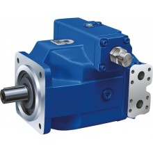
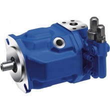
Directional spool valves, pilot operated, with electro-hydraulic actuation H-4WEH…XD
Доступно к заказу
Цена по запросу
И выбери подходящего.
Description
- Size 10 … 32
- Component series 4X, 7X, 6X
- Maximum operating pressure 350 bar
- Maximum flow 1100 l/min
- Area of application in accordance with the Explosion Protection Directive 2014/34/EU: I M2; II 2G
- Type of protection valve:
– Ex h I Mb X according to EN 80079-38
– Ex h IIC T4 Gb X according to EN 80079-36 - Type of protection, solenoid coil:
– Ex db I Mb nach EN 60079-1
– Ex db IIC T4 Gb nach EN 60079-1 - Solenoid coil certified according to IECEx
Features
- 4/3- or 4/2-way version
- For intended use in potentially explosive atmosphere
- Internal or external pilot control
- Subplate mounting
- Porting pattern according to ISO 4401
- Spring centering, spring end position or hydraulic end position
- Wet-pin DC solenoids
- Manual override
- Electrical connection as individual connection with cable gland
- Switching time adjustment, optional
- Preload valve in channel P of the main valve, optional
Product description
Type H-4WEH 16…XD...

The valve type H-4WEH is a directional spool valve with electro-hydraulic actuation. It controls the start, stop and direction of flow.
The directional valve basically consists of the main valve with housing (1), the main control spool (2), one or two return springs (3.1) and (3.2), as well as the pilot control valve (4) with one or two solenoids "a" (5.1) and/or "b" (5.2).
For unobjectionable functioning, the hydraulic system has to be bled properly.
The main control spool (2) in the main valve is held in the zero or initial position by the springs or by means of pressurization. In the initial position, the two spring chambers (6) and (8) are connected with the tank in a depressurized form via the pilot control valve (4). The pilot control valve is supplied with pilot oil via the control line (7). Supply can be effected internally or externally (externally via port X).
Upon actuation of the pilot control valve, e.g. solenoid "a", the pilot control spool (10) is moved to the left and thus, the spring chamber (8) is pressurized with pilot pressure. The spring chamber (6) remains depressurized.
The pilot pressure acts on the left side of the main control spool (2) and moves it against the spring (3.1). This connects ports P with B and A with T in the main valve.
When the solenoid is switched off, the pilot control spool returns into the initial position (except for impulse spool). The spring chamber (8) is unloaded to the tank.
The pilot oil from the spring chamber is displaced into channel Y via the pilot control valve.
The pilot oil supply and return can be effected internally or externally.
The manual override (9) allows the control spool (10) to be moved without solenoid energization.
Notice:
The main control spool (2) is held in a central position by the return springs (3.1) and (3.2) in spring chambers (6) and (8) without pilot pressure, even if the valve is positioned for example vertically.
Due to the design principle, internal leakage is inherent to the valves, which may increase over the life cycle.
Pilot oil supply
"H-WEH"
The pilot oil supply is effected externally via the X channel from a separate pressure supply.
The pilot oil return is effected externally via the Y channel into the tank.
"H-WEH…E…"
The pilot oil supply is effected internally from the P channel of the main valve.
The pilot oil return is effected externally via the Y channel into the tank. In the subplate, port X is closed.
"H-WEH…ET…"
The pilot oil supply is effected internally from the P channel of the main valve.
The pilot oil return is effected internally via the T channel into the tank. In the subplate, ports X and Y are closed.
"H-WEH…T…"
The pilot oil supply is effected externally via the X channel from a separate pressure supply.
The pilot oil return is effected internally via the T channel into the tank. In the subplate, port Y is closed.
Throttle insert
The use of the throttle insert is necessary if the pilot oil supply in the P channel of the pilot control valve is to be limited.

| 1 | Pilot control valve |
| 2 | Throttle insert |
| 3 | Seal ring |
Type code
| 01 | 02 | 03 | 04 | 05 | 06 | 07 | 08 | 09 | 10 | 11 | 12 | 13 | 14 | 15 | 16 | 17 | 18 | 19 | ||
| H | – | 4 | WEH | / | 6B | G24 | N | XD | Z2 |
| 01 | Up to 350 bar | H |
| 02 | 4-way version | 4 |
| Type of actuation | ||
| 03 | Electro-hydraulic | WEH |
| Size | ||
| 04 | NG10 | 10 |
| NG16 | 16 | |
| NG25 | 25 | |
| NG32 | 32 | |
| Control spool return main valve | ||
| 05 | By means of springs | no code |
| Hydraulic 1) | H | |
| 06 | Symbols; for the possible version, see "Symbols/Circuit diagrams" | e.g. C |
| 07 | Component series 40 … 49 (40 … 49: unchanged installation and connection dimension) – NG10 | 4X |
| Component series 60 … 69 (60 … 69: unchanged installation and connection dimension) – NG25 ("W.H 25") and NG32 | 6X | |
| Component series 70 … 79 (70 … 79: unchanged installation and connection dimension) – NG16 | 7X | |
| Control spool return in the pilot control valve with 2 spool positions and 2 solenoids (only possible with symbols C, D, K, Z and hydraulic control spool return in the main valve) | ||
| 08 | With spring return | no code |
| Without spring return | O | |
| Without spring return with detent | OF | |
| Pilot control valve | ||
| 09 | High-power valve | 6B |
| 10 | Direct voltage 24 V | G24 |
| 11 | With manual override | N |
| Explosion protection | ||
| 12 | "Flameproof enclosure", for details, please refer to the "information on explosion protection" | XD |
| Pilot oil flow | ||
| 13 | External pilot oil supply, external pilot oil return 2) | no code |
| Internal pilot oil supply, external pilot oil return 3) | E | |
| Pilot oil supply internal, pilot oil return internal 3) | ET | |
| External pilot oil supply, internal pilot oil return 2) | T | |
| Switching time adjustment | ||
| 14 | Without switching time adjustment | no code |
| Switching time adjustment as supply control | S | |
| Switching time adjustment as discharge control | S2 | |
| Electrical connection | ||
| 15 | Solenoid with terminal box and cable gland; for details please refer to "Electrical connection" | Z2 |
| Throttle insert | ||
| 16 | Without throttle insert | no code |
| Throttle Ø 0.8 mm | B08 | |
| Throttle Ø 1.0 mm | B10 | |
| Throttle Ø 1.2 mm | B12 | |
| Throttle Ø 1.5 mm | B15 | |
| preload valve (not for NG10) | ||
| 17 | Without preload valve | no code |
| With preload valve (pö = 4.5 bar) | P4,5 | |
| 18 | Without pressure reducing valve | no code |
| With pressure reducing valve 4) | D3 | |
| Seal material (observe compatibility of seals with hydraulic fluid used, see "Technical data") | ||
| 19 | NBR seals | no code |
| FKM seals | V | |
| 1) | 2 spool positions (hydraulic end position): only symbols C, D, K, Z, Y |
| 2) | Pilot oil supply X or return Y external: – Maximum pilot pressure: see "Technical data". – At a higher pilot pressure, version "D3" must be used. |
| 3) | Pilot oil supply internal (versions "ET" and "E"): – Minimum pilot pressure: see "Technical data". – Maximum pilot pressure: see "Technical data". – In order to prevent inadmissibly high pressure peaks, a throttle insert "B10" has to be provided in port P of the pilot control valve (see "Product description"). – Version "D3" must be used. |
| 4) | Only in connection with the "B10" throttle insert |
Notice:
The manual override cannot be allocated a safety function and may only be used up to a tank pressure of 50 bar.
Technical data
general
| Size | 10 | 16 | 25 | 32 | ||
| Weight | Valve with one solenoid | kg | 11 | 13.5 | 22 | 39 |
| Valve with two solenoids, spring-centered | kg | 14 | 16.5 | 25 | 42 | |
| Switching time adjustment "S" and "S2" | kg | 0.8 | ||||
| Pressure reducing valve "D3" | kg | 0.4 | ||||
| Installation position 1) | Any | |||||
| Ambient temperature range | °C | -20 … +80 | ||||
| Storage temperature range | °C | +5 … +40 | ||||
| Maximum storage time | Years | 1 | ||||
| Maximum admissible acceleration amax | g | 10 | ||||
| Surface protection | Galvanized | |||||
| MTTFD values according to EN ISO 13849 | Years | 100 | ||||
| 1) | With suspended installation, higher sensitivity to contamination, horizontal is recommended. For valves with hydraulic control spool return "H" and symbol C, D, K, Z, Y, horizontal is required. |
hydraulic
| Size | 10 | 16 | 25 | 32 | |||
| Maximum operating pressure | Port P | bar | 350 | ||||
| Anschluss A | bar | 350 | |||||
| Port B | bar | 350 | |||||
| Port T | External pilot oil return Y | bar | 250 | ||||
| Internal pilot oil return Y | bar | 210 | |||||
| Port Y | Pilot oil return, external | bar | 210 | ||||
| Maximum flow of the main valve | l/min | 160 | 300 | 700 | 1100 | ||
| Maximum pilot pressure | Port X | Standard | bar | 250 | |||
| Pressure reducing valve "D3" | bar | 350 | |||||
| Minimum pilot pressure | External or internal pilot oil supply X (symbols D, K, E, J, L, M, Q, R, U, W) | 3-spool position valve, spring-centered | bar | 12 | 14 | 13 | 8.5 |
| 2-spool position valve, spring end position | bar | 10 | 14 | 13 | 10 | ||
| 2-spool position valve, hydraulic end position | bar | 7 | 14 | 8 | 5 | ||
| Internal pilot oil supply X (symbols C, F, H, P, T, V, Z, S) 1) | bar | 7.5 2) | 4.5 3) | ||||
| Pilot volume for switching process | 3-spool position valve, spring-centered | cm³ | 2.04 | 5.72 | 14.2 | 29.4 | |
| 2-spool position valve | cm³ | 4.08 | 11.45 | 28.4 | 58.8 | ||
| Pilot volume for shortest switching time, approx. | l/min | 35 | 45 | ||||
| Hydraulic fluid | see table "Hydraulic fluid" | ||||||
| Hydraulic fluid temperature range | NBR seals | °C | -20 … +80 | ||||
| FKM seals | °C | -15 … +80 | |||||
| Viscosity range | mm²/s | 2.8 … 500 | |||||
| Maximum admissible degree of contamination of the hydraulic fluid, cleanliness class according to ISO 4406 (c) 4) | Class 20/18/15 | ||||||
| 1) | Symbol S only for NG16 |
| 2) | For symbols C, F, G, H, P, T, V, Z, an internal pilot oil supply is only possible if the flow from P → T in the central position (for 3-spool position valve) or while crossing the central position (for 2-spool position valve) is so large that the pressure differential of P → T reaches a value of at least 7.5 bar. At a pressure differential below 7.5 bar, a check valve with a cracking pressure of 7.5 bar must be installed in the return line to the tank. Pilot oil return Y must be realized externally. |
| 3) | For symbols C, F, G, H, P, T, V, Z, S (Symbol S only for Size 16) – by meansof a preload valve (not Size 10) or a correspondinglyhigh flow. |
| 4) | The cleanliness classes specified for the components must be adhered to in hydraulic systems. Effective filtration prevents faults and simultaneously increases the life cycle of the components. For the selection of the filters, see www.boschrexroth.com/filter. |
| Hydraulic fluid | Classification | Suitable sealing materials | Standards | data sheet | |
| Mineral oils | HL, HLP, HLPD | NBR, FKM | DIN 51524 | 90220 | |
| Bio-degradable | Insoluble in water | HETG | FKM | ISO 15380 | 90221 |
| HEES | FKM | ||||
| Soluble in water | HEPG | FKM | ISO 15380 | ||
| Flame-resistant | Containing water | HFC (Fuchs: Hydrotherm 46M, Renosafe 500; | NBR | ISO 12922 | 90223 |
|
Important information on hydraulic fluids:
| |||||
electrical
| Voltage type | Direct voltage | |
| Nominal voltage according to VDE 0580 | V | 24 / 110 |
| Voltage tolerance (nominal voltage) | % | ± 10 |
| Admissible residual ripple | % | < 5 |
| Duty cycle/operating mode according to VDE 0580 | S1 (continuous operation) | |
| Switching time according to ISO 6403 | See "switching times" table | |
| Maximum switching frequency | 1/h | 15000 |
| Maximum switch-off voltage peaks Solenoid 1) | V | 500 |
| Nominal power with ambient temperature 20 °C | W | 13 |
| Maximum power with 1.1 x nominal voltage and an ambient temperature of 20 °C | W | 15.8 |
| Protection class according to EN 60529 | IP65 (If a suitable and a correctly mounted mating connector are used.) | |
| 1) | Suitable damping by user required |
Information on explosion protection
| Application according to Explosion Protection Directive 2014/34/EU | I M2 | II 2G | |
| Type of protection valve 1) | Ex h I Mb X | Ex h IIC T4 Gb X | |
| Maximum surface temperature 2) | °C | 105 | |
| Temperature class | - | T4 | |
| Valve solenoid type of protection according to EN 60079-7 / EN 60079-18 | Ex db I Mb | Ex db IIC T4 Gb | |
| Baumusterprüfbescheinigung Magnet | BVS 03 ATEX E 300 X | ||
| “IECEx Certificate of Conformity” for solenoid | IECEx BVS 1191 X | ||
| 1) | Ex h: structural safety c according to EN 80079-37. |
| 2) | Surface temperature > 50 °C, provide contact protection. |
Special application conditions for a safe application
- Connection lines must be passed in a strain-relieved way. The first mounting point must be within 150 mm of the cable and line entry.
- In order to avoid dangers caused by static charge, the base and/or subplate on which the valve is to be fitted must be electrically conductive and included in the equipotential bonding.
- The valve solenoid must not be installed close to charge generating processes.
- Contact of the connection cable with the casing surface is to be prevented.
Switching times
| Pilot pressure | bar | 70 | 250 | Spring | |
| ON | OFF | ||||
| NG10 | Without throttle insert | ms | 50 … 70 | 50 … 70 | 30 … 40 |
| With throttle insert | ms | 70 … 100 | 60 … 80 | 30 … 40 | |
| NG16 | Without throttle insert | ms | 60 … 90 | 50 … 70 | 60 … 90 |
| With throttle insert | ms | 120 … 140 | 90 … 110 | 60 … 90 | |
| NG25 | Without throttle insert | ms | 80 … 110 | 60 ... 80 | 110 ... 140 |
| With throttle insert | ms | 210 …260 | 130 … 160 | 110 ... 140 | |
| NG32 | Without throttle insert | ms | 90 … 140 | 80 … 110 | 150 … 170 |
| With throttle insert | ms | 430 … 570 | 240 … 360 | 150 … 170 | |
Notices:
- Switching time = contacting at the pilot control valve until start of opening of the control edge in the main valve and change in the control spool stroke by 95 %
- The switching times are measured according to ISO 6403 with HLP46, ϑoil = 40 °C ±5 °C.
With different hydraulic fluid temperatures, variations may occur.
- The switching times increase by approx. 30 ms if the pressure reducing valve "D3" is used.
- The switching times have been determined under ideal conditions and may differ in the system, depending on the application conditions.
Free flow cross-sections in zero position with control spools Q, V and W
| Size | 10 | 16 | 25 | 32 | ||
| Symbol Q | A – T; B – T | mm² | 13 | 32 | 83 | 78 |
| Symbol V | A – T; B – T | mm² | 13 | 32 | 83 | 73 |
| P – A; P – B | mm² | 13 | 32 | 83 | 84 | |
| Symbol W | A – T; B – T | mm² | 2.4 | 6 | 14 | 20 |
Diagrams/characteristic curves
(measured with HLP46, ϑOil = 40 ±5 °C)
Size 10
Δp-qV characteristic curves

| Symbol | Spool position | Zero position | |||||
| P – A | P – B | A – T 1) | B – T 1) | A – T | B – T | P – T | |
| E, Y, D, Q, V, W, Z | 1 | 1 | 3 | 5 | – | – | – |
| F | 1 | 3 | 1 | 4 | 3 | – | 6 |
| G, T | 4 | 2 | 4 | 7 | – | – | 8 |
| H, C | 3 | 3 | 1 | 7 | 1 | 5 | 5 |
| J, K | 1 | 2 | 1 | 6 | – | – | – |
| L | 2 | 2 | 1 | 4 | 2 | – | – |
| M | 3 | 3 | 2 | 5 | – | – | – |
| P | 3 | 1 | 2 | 7 | – | 5 | 7 |
| R | 1 | 2 | 3 | – | – | – | – |
| U | 2 | 2 | 3 | 6 | – | 6 | – |
| 1) | The pressure differential refers to the use of port T. If port T1 is additionally used, the pressure differential maybe lower. If only port T1 is used, the relations A – T and B – T may be reversed. |
Performance limits
| 2-spool position valve – qV max in l/min | |||||
| Symbol | Operating pressure pmax in bar | ||||
| 70 | 140 | 210 | 280 | 350 | |
| X external – spring end position in the main valve 1) (at minimum pilot pressure of 12 bar) | |||||
| C, D, K, Y, Z | 160 | 160 | 160 | 160 | 160 |
| X external – hydraulic end position in the main valve | |||||
| HC, HD, HK, HZ, HY | 160 | 160 | 160 | 160 | 160 |
| 1) | If the pilot pressure fails, the function of the return spring is no longer guaranteed with the specified flow values. |
Performance limits
| 3-spool position valves – qV max in l/min | |||||
| Symbol | Operating pressure pmax in bar | ||||
| 70 | 140 | 210 | 280 | 350 | |
| X external – spring-centered | |||||
| E, J, L, M, Q, U, V, W, R | 160 | 160 | 160 | 160 | 160 |
| F, P | 160 | 120 | 100 | 90 | 90 |
| G, T | 160 | 160 | 160 | 130 | 120 |
| H | 160 | 160 | 120 | 110 | 100 |
Size 16
Δp-qV characteristic curves

| Symbol | Spool position | Zero position | |||||
| P –A | P – B | A – T | B – T | P – T | A – T | B – T | |
| D, E, Y | 1 | 1 | 3 | 3 | – | – | – |
| F | 1 | 2 | 5 | 5 | 4 | 3 | – |
| G | 4 | 1 | 5 | 5 | 7 | – | – |
| C, H | 1 | 1 | 5 | 6 | 2 | 4 | 4 |
| K, J | 2 | 2 | 6 | 6 | – | 3 | – |
| L | 2 | 2 | 5 | 4 | – | 3 | – |
| M | 1 | 1 | 3 | 4 | – | – | – |
| P | 2 | 1 | 3 | 6 | 5 | – | – |
| Q | 1 | 1 | 6 | 6 | – | – | – |
| R | 2 | 4 | 7 | – | – | – | – |
| S | 3 | 3 | 3 | – | 9 | – | – |
| T | 4 | 1 | 5 | 5 | 7 | – | – |
| U | 2 | 2 | 3 | 4 | – | – | 6 |
| V, Z | 1 | 1 | 6 | 6 | 10 | 8 | 8 |
| W | 1 | 1 | 3 | 4 | – | – | – |
Performance limits
| 2-spool position valve – qV max in l/min | |||||
| Symbol | Operating pressure pmax in bar | ||||
| 70 | 140 | 210 | 280 | 350 | |
| X external – spring end position in the main valve 1) (at minimum pilot pressure of 12 bar) | |||||
| C, D, K, Y, Z | 300 | 300 | 300 | 300 | 300 |
| X external – spring end position in the main valve | |||||
| C | 300 | 300 | 300 | 300 | 300 |
| D, Y | 300 | 270 | 260 | 250 | 230 |
| K | 300 | 250 | 240 | 230 | 210 |
| Z | 300 | 260 | 190 | 180 | 160 |
| X external – hydraulic end position in the main valve | |||||
| HC, HD, HK, HZ, HY | 300 | 300 | 300 | 300 | 300 |
| 1) | If the specified flow values are exceeded, the function of the return spring is no longer guaranteed if the pilot pressure fails. |
Performance limits
| 3-spool position valves – qV max in l/min | |||||
| Symbol | Operating pressure pmax in bar | ||||
| 70 | 140 | 210 | 280 | 350 | |
| X external – spring-centered | |||||
| E, H, J, L, M, Q, U, W, R | 300 | 300 | 300 | 300 | 300 |
| F, P | 300 | 250 | 180 | 170 | 150 |
| G, T | 300 | 300 | 240 | 210 | 190 |
| S | 300 | 300 | 300 | 250 | 220 |
| V | 300 | 250 | 210 | 200 | 180 |
Size 25
Δp-qV characteristic curves

| Symbol | Spool position | Zero position | ||||||
| P – A | P – B | A – T | B – T | B – A | A – T | B – T | P – T | |
| E, Y, D | 1 | 1 | 3 | 4 | – | – | – | – |
| F | 1 | 1 | 2 | 4 | – | 2 | – | 5 |
| G, T | 1 | 1 | 2 | 5 | – | – | – | 7 |
| H | 1 | 1 | 2 | 5 | – | 2 | 2 | 4 |
| C | 1 | 1 | 2 | 5 | – | – | – | – |
| J | 1 | 1 | 2 | 5 | – | 6 | 5 | – |
| K | 1 | 1 | 2 | 5 | – | – | – | – |
| L | 1 | 1 | 2 | 4 | – | 5 | – | – |
| M | 1 | 1 | 3 | 4 | – | – | – | – |
| P | 1 | 1 | 3 | 5 | – | – | 3 | 5 |
| Q | 1 | 1 | 2 | 3 | – | – | – | – |
| R | 1 | 1 | 3 | – | 8 | – | – | – |
| U | 1 | 1 | 2 | 5 | – | – | 5 | – |
| V | 1 | 1 | 2 | 5 | – | 8 | 7 | – |
| Z | 1 | 1 | 2 | 5 | – | – | – | – |
| W | 1 | 1 | 3 | 4 | – | – | – | – |
| 8 Symbol R, spool position B – A |
Performance limits
| 2-spool position valve – qV max in l/min | |||||
| Symbol | Operating pressure pmax in bar | ||||
| 70 | 140 | 210 | 280 | 350 | |
| X external – spring end position in the main valve 1) (at minimum pilot pressure of 13 bar) | |||||
| C, D, K, Y, Z | 700 | 700 | 700 | 700 | 650 |
| X external – spring end position in the main valve 1) | |||||
| C | 700 | 700 | 700 | 700 | 650 |
| D, Y | 700 | 650 | 400 | 350 | 300 |
| K | 700 | 650 | 420 | 370 | 320 |
| Z | 700 | 700 | 650 | 480 | 400 |
| X external – hydraulic end position in the main valve | |||||
| HC, HD, HK, HZ, HY | 700 | 700 | 700 | 700 | 700 |
| HC./O…, HD./O…, HK./O…, HZ./O… | 700 | 700 | 700 | 700 | 700 |
| HC./OF…, HD./OF…, HK./OF…, HZ./OF… | 700 | 700 | 700 | 700 | 700 |
| 1) | If the specified flow values are exceeded, the function of the return spring is no longer guaranteed if the pilot pressure fails. |
Performance limits
| 3-spool position valves – qV max in l/min | |||||
| Symbol | Operating pressure pmax in bar | ||||
| 70 | 140 | 210 | 280 | 350 | |
| X external – spring-centered | |||||
| E, L, M, Q, U, W | 700 | 700 | 700 | 700 | 650 |
| G, T | 400 | 400 | 400 | 400 | 400 |
| F | 650 | 550 | 430 | 330 | 300 |
| H | 700 | 650 | 550 | 400 | 360 |
| J | 700 | 700 | 650 | 600 | 520 |
| P | 650 | 550 | 430 | 430 | 300 |
| V | 650 | 550 | 400 | 350 | 310 |
| R | 700 | 700 | 700 | 650 | 580 |
Size 32
Δp-qV characteristic curves

| Symbol | Spool position | |||||
| P – A | P – B | A – T | B – T | B – A | P – T | |
| E | 4 | 4 | 3 | 2 | – | – |
| R | 4 | 4 | 3 | – | 1 | – |
| W | 4 | 4 | 3 | 2 | – | – |
| G, T | 7 | 8 | 7 | 5 | – | 6 |
Performance limits
| 2-spool position valve – qV max in l/min | |||||
| Symbol | Operating pressure pmax in bar | ||||
| 70 | 140 | 210 | 280 | 350 | |
| X external – spring end position in the main valve 1) (at minimum pilot pressure of 10 bar) | |||||
| C, D, K, Y, Z | 1100 | 1040 | 860 | 750 | 680 |
| X external – spring end position in the main valve 1) | |||||
| C | 1100 | 1040 | 860 | 800 | 700 |
| D, Y | 1100 | 1040 | 540 | 480 | 420 |
| K | 1100 | 1040 | 860 | 500 | 450 |
| Z | 1100 | 1040 | 860 | 700 | 650 |
| X external – hydraulic end position in the main valve | |||||
| HC, HD, HK, HZ, HY | 1100 | 1040 | 860 | 750 | 680 |
| 1) | If the specified flow values are exceeded, the function of the return spring is no longer guaranteed if the pilot pressure fails. |
Performance limits
| 3-spool position valves – qV max in l/min | |||||
| Symbol | Operating pressure pmax in bar | ||||
| 70 | 140 | 210 | 280 | 350 | |
| X external – spring-centered | |||||
| E, J, L, M, Q, R, U, W | 1100 | 1040 | 860 | 750 | 680 |
| G, T, H, F, P | 900 | 900 | 800 | 650 | 450 |
| V | 1100 | 1000 | 680 | 500 | 450 |
Performance limits : Important information
Notice (applies to all sizes):
The specified performance limits apply to the use with two directions of flow (e. g. from P to A and simultaneous return flow from B to T at a ratio of 1:1). Due to the flow forces acting within the valves, the admissible performance limit may be considerably lower with only one direction of flow (e. g. from P to A while port B is blocked, with flow in the same or in different directions). In such cases of use, please consult us.
The performance limit was determined when the solenoids were at operating temperature, at 10 % undervoltage and without tank preloading.
| NG16 |
|
| NG25 |
|
| NG32 |
|
Symbols/Circuit diagrams
load errorElectrical connection
load errorDimensions
load errorProject planning information
load errorDownloads
| Directional spool valves, pilot-operated, with electro-hydraulic actuation Data Sheet | RE24751-XD | 2020-07-01 | English | PDF | 1.1MB Product Groups: Pilot operated Type H-4WEH …XD | |
| 4/2 and 4/3 directional valves, internally pilot-operated, externally pilot-operated, Type H-4WEH...XD..., Operating instructions Manual | RE24751-XD-B | 2020-07-01 | English | PDF | 1.8MB Product Groups: Pilot operated | |
| Explosion-protected hydraulic products for industrial and mobile applications Brochure | R999000373 | 2017-03-01 | English | PDF | 5.8MB Product Groups: Pumps, CD - single rod cylinder, Proportional, high-response and servo valves, Axial piston pumps, Mobile controls Product overview |


Нет отзывов об этом товаре.