 H-.WMRH")
Артикул: RX7413
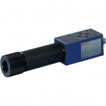
Directional spool valves, pilot operated, with mechanical-hydraulic actuation (roller plunger) H-.WMRH
Доступно к заказу
Цена по запросу
И выбери подходящего.
Description
- Size 10, 16, 25 (4W.H22), 25 (4W.H25), 32
- Component series 4X, 7X, 6X
- Maximum operating pressure 350 bar
- Maximum flow 1100 l/min
Features
- Type of actuation: Roller plunger
- For subplate mounting
- Porting pattern according to ISO 4401
- Subplates according to data sheets 45054 to 45060 (separate order)
- Spring centering, spring end position or hydraulic end position
- Optional auxiliary operating device
- Switching time adjustment, optional
- Preload valve in channel P of the main valve, optional
- Stroke setting at main spool, optional
- Stroke setting and/or end position control, optional
- Inductive position switch and proximity sensors (contactless)
Product description
Type 4WMMH …

Valves of type H–.WMRH are directional spool valves with mechanical-hydraulic actuation. They control the start, stop and direction of a flow.
The directional valves basically consist of the main valve with housing (1), the main control spool (2), one or two return springs (3.1) and (3.2), as well as the pilot control valve (4).
The function of the valves corresponds to the function of valves of type WPH. The pilot control valve is, however, actuated mechanically.
Pilot oil supply
NG10

Pilot oil supply
NG16

Pilot oil supply
NG25 (type 4W.H 22 .7X/…)

Pilot oil supply
NG25 (type 4W.H 25 .6X/…)

Pilot oil supply
Size 32


Attention!
The pilot oil supply may only be modified by authorized specialists or at the factory!
– External pilot oil supply X or return Y :
- with NG10, version SO30 has to be used if sandwich plates are installed. The identification SO30 has to be used at the end of the type designation (sandwich plate).
- the maximum admissible operating parameters of the pilot control valve must be observed!
- maximum pilot pressure: please observe Technical data!
– Internal pilot oil supply (version “ET” and “E”):
- minimum pilot pressure: please observe Technical data!
- to prevent inadmissibly high pressure peaks, a “B10” throttle insert must be provided in port P of the pilot control valve.
- in connection with version “H-”, the “D3” pressure reducing valve (see Pressure reducing valve) has to be installed in addition.
Type code
| 01 | 02 | 03 | 04 | 05 | 06 | 07 | 08 | 09 | 10 | 11 | 12 | 13 | 14 | 15 | 16 | 17 | 18 | 19 | ||
| H – | WMRH | / | 6 | / | * |
| 01 | Up to 350 bar 1; 2) | H – |
| 02 | 3-way version | 3 |
| 4-way version | 4 | |
| Types of actuation | ||
| 03 | mechanical-hydraulic: Roller plunger | WMRH |
| Size | ||
| 04 | NG10 | 10 |
| NG16 | 16 | |
| NG25 (type 4W.H 22 .7X/…) | 22 | |
| NG25 (type 4W.H 25 .6X/…) | 25 | |
| Size 32 | 32 | |
| Spool return in the main valve | ||
| 05 | By means of springs | no code |
| hydraulic 3) | H | |
| 06 | Symbols; for the possible version, see "Symbols/Circuit diagrams" | |
| Component series | ||
| 07 | 40 to 49 – NG10 (40 to 49: unchanged installation and connection dimensions) | 4X |
| 60 to 69 – NG25 (4W.H 25.) and NG32 (60 to 69: unchanged installation and connection dimensions) | 6X | |
| 70 to 79 – NG16 (from series 72) and NG25 (4W.H 22.) (70 to 79: unchanged installation and connection dimensions) | 7X | |
| Spool return in the pilot control valve with 2 spool positions only possible with spools B, C, D and hydraulic control spool return in the main valve: | ||
| 08 | With spring return | no code |
| Pilot control valve | ||
| 09 | with mechanical, manual actuation | 6 |
| 10 | Without manual override | no code |
| 11 | External pilot oil supply, external pilot oil return 1) | no code |
| Internal pilot oil supply, external pilot oil return 1; 2) | E | |
| Pilot oil supply internal, pilot oil return internal 2) | ET | |
| External pilot oil supply, internal pilot oil return 1) | T | |
| 12 | Without switching time adjustment | no code |
| Switching time adjustment as supply control | S | |
| Switching time adjustment as discharge control | S2 | |
| Spool position monitoring | ||
| 13 | Without position switch | no code |
| Monitored spool position "a" | QMAG24 | |
| Monitored spool position "b" | QMBG24 | |
| Monitored spool position "a" and "b" | QMABG24 | |
| Monitored rest position | QM0G24 | |
| 14 | Stroke setting see stroke setting in type key table | |
| Throttle insert | ||
| 15 | Without throttle insert | no code |
| Throttle Ø 0.8 mm | B08 | |
| Throttle Ø 1.0 mm | B10 | |
| Throttle Ø 1.2 mm | B12 | |
| Throttle Ø 1.5 mm | B15 | |
| Throttle Ø 2.0 mm | B20 | |
| Throttle Ø 2.5 mm | B25 | |
| preload valve (not for NG10) 4) | ||
| 16 | without preload valve | no code |
| with preload valve (pö = 4.5 bar) | P4,5 | |
| 17 | without pressure reducing valve | no code |
| With pressure reducing valve | D3 4) | |
| Seal material | ||
| 18 | NBR seals | no code |
| FKM seals (other seals upon request) | V | |
| Observe compatibility of seals with hydraulic fluid used. | ||
| 19 | Information in the plain text | * |
| 1) External pilot oil supply X or return Y: | |
| – with NG10, version SO30 has to be used if sandwich plates are installed. The identification SO30 has to be used at the end of the type designation (sandwich plate). | |
| – the maximum admissible operating parameters of the pilot control valve must be observed! | |
| – observe the maximum pilot pressure! | |
| 2) Internal pilot oil supply (version “ET” and “E”): | |
| – minimum pilot pressure: please observe Technical data! | |
| – to prevent inadmissibly high pressure peaks, a “B10” throttle insert must be provided in port P of the pilot control valve (see Pilot oil supply). | |
| – in connection with version “H”, the “D3” pressure reducing valve must be installed in addition. | |
| 3) 2 spool positions (hydraulic end position): only piston C, D, Y, K ,Z | |
| 4) only in connection with throttle insert “B10” |
| pSt | Pilot pressure |
| ppilot min | Pilot pressure, minimum |
| ptank | Tank pressure |
| pö | Cracking pressure |
Preferred types and standard units are contained in the EPS (standard price list).
Technical data
general
| Size | 10 | 16 | 25 (4W.H22) | 25 (4W.H25) | 32 | ||
| Weight (approx.) | kg | 6.4 | 8.5 | 11.5 | 17.6 | ||
| Switching time adjustment | kg | 0.8 | |||||
| Pressure reducing valve | kg | 0.4 | |||||
| Installation position | any; horizontal with valves with hydraulic control spool return “H” and spool symbol B, C, D, K, Z, Y | ||||||
| Ambient temperature range | °C | -30 … +50 | |||||
| Storage temperature range | °C | -20 … +70 | |||||
| Surface protection | Valve body | Coating, layer thickness max. 100 μm | |||||
hydraulic
| Size | 10 | 16 | 25 (4W.H22) | 25 (4W.H25) | 32 | |||
| Maximum operating pressure | Port P | bar | 350 | |||||
| Anschluss A | bar | 350 | ||||||
| Port B | bar | 350 | ||||||
| Port T | External pilot oil return Y | bar | 315 | 250 | ||||
| Internal pilot oil return Y 1) | bar | 60 | ||||||
| Port Y | Pilot oil return, external | bar | 60 | |||||
| Hydraulic fluid 2) | see table | |||||||
| Hydraulic fluid temperature range | NBR seals | °C | -30 … +80 | |||||
| FKM seals | °C | -20 … +80 | ||||||
| Viscosity range | mm²/s | 2.8 … 500 | ||||||
| Maximum admissible degree of contamination of the hydraulic fluid 3) | Class 20/18/15 according to ISO 4406 (c) | |||||||
| Maximum pilot pressure 4) | bar | 250 | 210 | 250 | ||||
| Minimum pilot pressure | External or internal pilot oil supply X (with control spool D, K, E, J, L, M, Q, R, U, W) | 3-spool position valve, spring-centered | bar | 10 | 14 | 12.5 | 13 | 8.5 |
| 3-spool position valve, pressure-centered | bar | - | 14 | - | 18 | 8.5 | ||
| 2-spool position valve with spring end position | bar | 10 | 14 | 13 | 10 | |||
| 2-spool position valve with hydraulic end position | bar | 7 | 14 | 8 | 5 | |||
| Internal pilot oil supply X (with control spool C, F, G, H, P, T, V, Z, S) | bar | 4.5 5) | 4.5 6) 7) | 4.5 7) | ||||
| Pilot volume for switching process | 3-spool position valve, spring-centered | cm³ | 2.04 | 5.72 | 7.64 | 14.2 | 29.4 | |
| 2-spool position valve | from zero position in switching position “a” | cm³ | 4.08 | 11.45 | 15.28 | 28.4 | 58.8 | |
| from switching position “a” in zero position | cm³ | - | 2.9 | - | 7 | 15.1 | ||
| from zero position in switching position “b” | cm³ | - | 5.72 | - | 14.15 | 29.4 | ||
| from switching position “b” in zero position | cm³ | - | 2.83 | - | 5.73 | 14.4 | ||
| Pilot flow for shortest switching time, approx. | l/min | 35 | 45 | |||||
| 1) | As a 3-spool position valve, pressure-centered only possible if ppilot ≥ 2 x ptank + ppilot min |
| 2) | The ignition temperature of the process and operating medium used must be over the maximum solenoid surface temperature. |
| 3) | The cleanliness classes specified for the components must be adhered to in hydraulic systems. Effective filtration prevents faults and simultaneously increases the life cycle of the components. For the selection of the filters, see www.boschrexroth.com/filter. |
| 4) | Internal pilot oil supply: With a higher pilot pressure, use of a pressure reducing valve is required. In connection with version “H-”, the “D3” pressure reducing valve must be additionally provided. (If it is not used, pilot pressure = operating pressure at the port) External pilot oil return: In connection with version “H-”, compliance with the maximum pilot pressure must be ensured by appropriate measures (e. g. protection of the separate pilot oil circuit by means of a pressure relief valve)! |
| 5) | For symbols C, F, G, H, P, T, V, Z, an internal pilot oil supply is only possible if the flow from P → T in the central position (for 3-spool position valve) or while crossing the central position (for 2-spool position valve) is so large that the pressure differential of P → T reaches a value of at least 6.5 bar. |
| 6) | Spool S only for NG16 |
| 7) | For spools C, F, G,J, H, P, T, V, Z, S – by means of preload valve (not NG10) or correspondingly high flow. (Determination of the required flow, see preload valve) |
| Hydraulic fluid | Classification | Suitable sealing materials | Standards | |
| Mineral oil | HL, HLP | FKM, NBR | DIN 51524 | |
| Bio-degradable | Insoluble in water | HEES (synthetic esters) | FKM | VDMA 24568 |
| HETG (rape seed oil) | FKM, NBR | |||
| Soluble in water | HEPG (polyglycols) | FKM | VDMA 24568 | |
| Other hydraulic fluids on request | ||||
Free flow cross-sections in zero position with spools Q, V and W
| Size | 10 | 16 | 25 (4W.H22) | 25 (4W.H25) | 32 | ||
| Spool Q | A – T; B – T | mm² | 13 | 32 | 78 | 83 | 78 |
| Spool V | P – A | mm² | 13 | 32 | 73 | 83 | 73 |
| A – T; B – T | mm² | 13 | 32 | 84 | 83 | 84 | |
| Spool W | A – T; B – T | mm² | 2.4 | 6 | 10 | 14 | 20 |
Inductive position switch type QM: electrical connection
The electric connection is realized via a 4-pole mating connector (separate order) with connection thread M12 x 1.
electrical
| Connection voltage (DC voltage) | V | 24 | ||
| Voltage tolerance (connection voltage) | +30 %/-15 % | |||
| Admissible residual ripple | % | ≤ 10 | ||
| Max. load capacity | mA | 400 | ||
| Switching outputs  | PNP transistor outputs, load between switching outputs and GND | |||
| Pinout  | 1 | V | 24 | |
| 2, 4 | Switching output | mA | 400 | |
| 3 | Earthing (GND) | V | 0 | |
(For applications outside these values, please consult us!)
Diagrams/characteristic curves
(measured with HLP46, ϑOil = 40 °C ± 5 °C)
Size 10
Δp-qV characteristic curves

| Piston | Spool position | Piston | Zero position | |||||
| P – A | P – B | A – T | B – T | A – T | B – T | P – T | ||
| E, Y, D | 2 | 2 | 4 | 5 | ||||
| F | 1 | 4 | 1 | 4 | F | 3 | – | 6 |
| G, T | 4 | 2 | 2 | 6 | G, T | – | – | 7 |
| H, C | 4 | 4 | 1 | 4 | H | 1 | 3 | 5 |
| J, K | 1 | 2 | 1 | 3 | ||||
| L | 2 | 3 | 1 | 4 | L | 3 | – | – |
| M | 4 | 4 | 3 | 4 | ||||
| P | 4 | 1 | 3 | 4 | P | – | 7 | 5 |
| Q, V, W, Z | 2 | 2 | 3 | 5 | ||||
| R | 2 | 2 | 3 | – | ||||
| U | 3 | 3 | 3 | 4 | U | – | 4 | – |
| B | 2 | 2 | – | – | ||||
Performance limits: (measured with HLP46, ϑoil = 40 ±5 °C)
NG10
| 2-spool position valve – qV max | |||
| Piston | Operating pressure pmax in bar | ||
| 200 bar | 250 bar | 315 bar | |
| E, J, L, M, Q, R, U, V, W, C, D, K, Z, Y | 160 l/min | 160 l/min | 160 l/min |
| H | 160 l/min | 150 l/min | 120 l/min |
| G, T | 160 l/min | 160 l/min | 140 l/min |
| F, P | 160 l/min | 140 l/min | 120 l/min |
Size 16
Δp-qV characteristic curves

| Symbol | Spool position | Zero position | |||||
| P – A | P – B | A – T | B – T | P – T | A – T | B – T | |
| D, E, Y | 1 | 1 | 3 | 3 | |||
| F | 1 | 2 | 5 | 5 | 4 | 3 | – |
| G | 4 | 1 | 5 | 5 | 7 | – | – |
| C, H | 1 | 1 | 5 | 6 | 2 | 4 | 4 |
| K, J | 2 | 2 | 6 | 6 | – | 3 | – |
| L | 2 | 2 | 5 | 4 | – | 3 | – |
| M | 1 | 1 | 3 | 4 | |||
| P | 2 | 1 | 3 | 6 | 5 | – | – |
| Q | 1 | 1 | 6 | 6 | |||
| R | 2 | 4 | 7 | – | |||
| S | 3 | 3 | 3 | – | 9 | – | – |
| T | 4 | 1 | 5 | 5 | 7 | – | – |
| U | 2 | 2 | 3 | 4 | 6 | ||
| V, Z | 1 | 1 | 6 | 6 | 10 | 8 | 8 |
| W | 1 | 1 | 3 | 4 | |||
Performance limits: (measured with HLP46, ϑoil = 40 ±5 °C)
NG16
| 2-spool position valve – qV max | |||||
| Piston | Operating pressure pmax in bar | ||||
| 70 bar | 140 bar | 210 bar | 280 bar | 350 bar | |
| X external, spring end position in the main valve | |||||
| C, D, K, Y, Z | 300 l/min | 300 l/min | 300 l/min | 300 l/min | 300 l/min |
| X external – spring end position in the main valve 1) | |||||
| C | 300 l/min | 300 l/min | 300 l/min | 300 l/min | 300 l/min |
| D, Y | 300 l/min | 270 l/min | 260 l/min | 250 l/min | 230 l/min |
| K | 300 l/min | 250 l/min | 240 l/min | 230 l/min | 210 l/min |
| Z | 300 l/min | 260 l/min | 190 l/min | 180 l/min | 160 l/min |
| X external – hydraulic end position in the main valve | |||||
| HC, HD, HK, HZ, HY | 300 l/min | 300 l/min | 300 l/min | 300 l/min | 300 l/min |
| Attention! | |
| 1) If the specified flow values are exceeded, the function of the return spring is no longer guaranteed if the pilot pressure fails! |
| 3-spool position valve – qV max | |||||
| Piston | Operating pressure pmax in bar | ||||
| 70 bar | 140 bar | 210 bar | 280 bar | 350 bar | |
| X external – spring-centered | |||||
| E, H, J, L, M, Q, U, W, R | 300 l/min | 300 l/min | 300 l/min | 300 l/min | 300 l/min |
| F, P | 300 l/min | 250 l/min | 180 l/min | 170 l/min | 150 l/min |
| G, T | 300 l/min | 300 l/min | 240 l/min | 210 l/min | 190 l/min |
| S | 300 l/min | 300 l/min | 300 l/min | 250 l/min | 220 l/min |
| V | 300 l/min | 250 l/min | 210 l/min | 200 l/min | 180 l/min |
| X external – pressure-centered (at minimum pilot pressure of 16 bar) | |||||
| all spools 2) | 300 l/min | 300 l/min | 300 l/min | 300 l/min | 300 l/min |
| 2) With spool V, the pilot control valve is not required for flows > 160 l/min. | |
(measured with HLP46, ϑOil = 40 °C ± 5 °C)
Size 25 (type W.H 22)
Δp-qV characteristic curves

| Piston | Spool position | Piston | Zero position | ||||||
| P – A | P – B | A – T | B – T | B – A | A – T | B – T | P – T | ||
| C, E, M, P, Q, U, V, Z | 2 | 2 | 1 | 4 | – | F | – | – | 4 |
| F | 1 | 2 | 1 | 2 | – | G, P | – | – | 6 |
| G, T | 2 | 2 | 2 | 4 | – | H | – | – | 2 |
| H, J, W, K, D | 2 | 2 | 1 | 3 | – | L | 4 | – | – |
| L | 2 | 2 | 1 | 2 | – | T | – | – | 5 |
| R | 1 | 2 | 1 | – | 5 | U | – | 6 | – |
| B | 2 | 2 | – | – | – | ||||
Performance limits: (measured with HLP46, ϑoil = 40 ±5 °C)
NG25 (type W.H 22)
| 2-spool position valve – qV max | |||||
| Piston | Operating pressure pmax in bar | ||||
| 70 bar | 140 bar | 210 bar | 280 bar | 350 bar | |
| X external – spring end position in the main valve (with ppilot min = 11 bar / 14 bar) | |||||
| C, D, K, Y, Z | 450 l/min | 450 l/min | 450 l/min | 450 l/min | 450 l/min |
| X external – spring end position in the main valve 1) | |||||
| C | 450 l/min | 450 l/min | 320 l/min | 250 l/min | 200 l/min |
| D, Y | 450 l/min | 450 l/min | 450 l/min | 400 l/min | 320 l/min |
| K | 450 l/min | 215 l/min | 150 l/min | 120 l/min | 100 l/min |
| Z | 350 l/min | 300 l/min | 290 l/min | 260 l/min | 160 l/min |
| X external – hydraulic end position in the main valve | |||||
| HC, HD, HK, HZ, HY | 450 l/min | 450 l/min | 450 l/min | 450 l/min | 450 l/min |
| 3-spool position valve – qV max | |||||
| Piston | Operating pressure pmax in bar | ||||
| 70 bar | 140 bar | 210 bar | 280 bar | 350 bar | |
| X external – spring-centered | |||||
| E, J, L, M, Q, U, W, R | 450 l/min | 450 l/min | 450 l/min | 450 l/min | 450 l/min |
| H | 450 l/min | 450 l/min | 300 l/min | 260 l/min | 230 l/min |
| G | 400 l/min | 350 l/min | 250 l/min | 200 l/min | 180 l/min |
| F | 450 l/min | 270 l/min | 175 l/min | 130 l/min | 110 l/min |
| V | 450 l/min | 300 l/min | 240 l/min | 220 l/min | 160 l/min |
| T | 400 l/min | 300 l/min | 240 l/min | 200 l/min | 160 l/min |
| P | 450 l/min | 270 l/min | 180 l/min | 170 l/min | 110 l/min |
(measured with HLP46, ϑOil = 40 °C ± 5 °C)
Size 25 (type W.H 25)
Δp-qV characteristic curves

| Symbol | Spool position | Zero position | |||||
| P – A | P – B | A – T 1) | B – T 1) | A – T | B – T | P – T | |
| E, Y, D | 1 | 1 | 3 | 4 | |||
| F | 1 | 1 | 2 | 4 | 2 | – | 5 |
| G, T | 1 | 1 | 2 | 5 | – | – | 7 |
| H | 1 | 1 | 2 | 5 | 2 | 2 | 4 |
| C | 1 | 1 | 2 | 5 | |||
| J | 1 | 1 | 2 | 5 | 6 | 5 | – |
| K | 1 | 1 | 2 | 5 | |||
| L | 1 | 1 | 2 | 4 | 5 | – | – |
| M | 1 | 1 | 3 | 4 | |||
| P | 1 | 1 | 3 | 5 | – | 3 | 5 |
| Q | 1 | 1 | 2 | 3 | |||
| R | 1 | 1 | 3 | – | |||
| U | 1 | 1 | 2 | 5 | – | 5 | – |
| V | 1 | 1 | 2 | 5 | 8 | 7 | – |
| Z | 1 | 1 | 2 | 5 | |||
| W | 1 | 1 | 3 | 4 | |||
| 8 Symbol R, spool position B – A | |||||||
| 1) | The pressure differential refers to the use of port T. If port T1 is additionally used, the pressure differential maybe lower. If only port T1 is used, the relations A – T and B – T may be reversed. |
| 7 | Spool G central position P – T |
| 8 | Spool T central position P – T |
Performance limits: (measured with HLP46, ϑoil = 40 ±5 °C)
NG25 (type W.H 25)
| 2-spool position valve – qV max | |||||
| Piston | Operating pressure pmax in bar | ||||
| 70 bar | 140 bar | 210 bar | 280 bar | 350 bar | |
| X external – spring end position in the main valve (with ppilotmin = 13 bar) | |||||
| C, D, K, Y, Z | 700 l/min | 700 l/min | 700 l/min | 700 l/min | 650 l/min |
| X external – spring end position in the main valve 1) | |||||
| C | 700 l/min | 700 l/min | 700 l/min | 700 l/min | 650 l/min |
| D, Y | 700 l/min | 650 l/min | 400 l/min | 350 l/min | 300 l/min |
| K | 700 l/min | 650 l/min | 420 l/min | 370 l/min | 320 l/min |
| Z | 700 l/min | 700 l/min | 650 l/min | 480 l/min | 400 l/min |
| X external – hydraulic end position in the main valve | |||||
| HC, HD, HK, HZ, HY | 700 l/min | 700 l/min | 700 l/min | 700 l/min | 700 l/min |
| 3-spool position valve – qV max | |||||
| Piston | Operating pressure pmax in bar | ||||
| 70 bar | 140 bar | 210 bar | 280 bar | 350 bar | |
| X external – spring-centered | |||||
| E, L, M, Q, U, W | 700 l/min | 700 l/min | 700 l/min | 700 l/min | 650 l/min |
| G, T | 400 l/min | 400 l/min | 400 l/min | 400 l/min | 400 l/min |
| F | 650 l/min | 550 l/min | 430 l/min | 330 l/min | 300 l/min |
| H | 700 l/min | 650 l/min | 550 l/min | 400 l/min | 360 l/min |
| J | 700 l/min | 700 l/min | 650 l/min | 600 l/min | 520 l/min |
| p | 650 l/min | 550 l/min | 430 l/min | 330 l/min | 300 l/min |
| V | 650 l/min | 550 l/min | 400 l/min | 350 l/min | 310 l/min |
| R | 700 l/min | 700 l/min | 700 l/min | 650 l/min | 580 l/min |
| X external – pressure-centered (at minimum pilot pressure of 18 bar) | |||||
| E, F, H, J, L, M, P, Q, R, U, V, W | 700 l/min | 700 l/min | 700 l/min | 700 l/min | 650 l/min |
| G, T | 400 l/min | 400 l/min | 400 l/min | 400 l/min | 400 l/min |
| X external – pressure-centered (with pilot pressure > 30 bar) | |||||
| G, T | 700 l/min | 700 l/min | 700 l/min | 700 l/min | 650 l/min |
| Attention! | |
| 1) If the specified flow values are exceeded, the function of the return spring is no longer guaranteed if the pilot pressure fails! |
(measured with HLP46, ϑOil = 40 °C ± 5 °C)
Size 32
∆p-qv-characteristic curves – Symbol E, R and W

| Piston | Spool position | ||||
| P – A | P – B | A – T | B – T | B – A | |
| E | 4 | 4 | 3 | 2 | – |
| R | 4 | 4 | 3 | – | 1 |
| W | 4 | 4 | 3 | 2 | – |
Size 32
∆p-qv- characteristic curves – Symbol G and T

| Piston | Spool position | ||||
| P – A | P – B | A – T | B – T | P – T | |
| G | 7 | 8 | 7 | 5 | 6 |
| T | 7 | 8 | 7 | 5 | 6 |
Performance limits: (measured with HLP46, ϑoil = 40 ±5 °C)
Size 32
| 2-spool position valve – qV max | |||||
| Piston | Operating pressure pmax in bar | ||||
| 70 bar | 140 bar | 210 bar | 280 bar | 350 bar | |
| X external – spring end position in the main valve (with ppilot min = 10 bar) | |||||
| C, D, K, Y, Z | 1100 l/min | 1040 l/min | 860 l/min | 750 l/min | 680 l/min |
| X external – spring end position in the main valve 1) | |||||
| C | 1100 l/min | 1040 l/min | 860 l/min | 800 l/min | 700 l/min |
| D, Y | 1100 l/min | 1040 l/min | 540 l/min | 480 l/min | 420 l/min |
| K | 1100 l/min | 1040 l/min | 860 l/min | 500 l/min | 450 l/min |
| Z | 1100 l/min | 1040 l/min | 860 l/min | 700 l/min | 650 l/min |
| X external – hydraulic end position in the main valve | |||||
| HC, HD, HK, HZ, HY | 1100 l/min | 1040 l/min | 860 l/min | 750 l/min | 680 l/min |
| 3-spool position valve – qV max | |||||
| Piston | Operating pressure pmax in bar | ||||
| 70 bar | 140 bar | 210 bar | 280 bar | 350 bar | |
| X external – spring-centered | |||||
| E, J, L, M, Q, U, W | 1100 l/min | 1040 l/min | 860 l/min | 750 l/min | 680 l/min |
| G, T, H, F, P | 900 l/min | 900 l/min | 800 l/min | 650 l/min | 450 l/min |
| V | 1100 l/min | 1000 l/min | 680 l/min | 500 l/min | 450 l/min |
| X external – pressure-centered (at minimum pilot pressure of 8.5 bar) | |||||
| all spools | 1100 l/min | 1040 l/min | 860 l/min | 750 l/min | 680 l/min |
| 1) If the specified flow values are exceeded, the function of the return spring is no longer guaranteed if the pilot pressure fails! |
Performance limits: important information
Notice (applies to all sizes):
The specified switching power limits apply to the use with two directions of flow (e. g. from P to A and simultaneous return flow from B to T at a ratio of 1:1). Due to the flow forces acting within the valves, the admissible switching power limit may be considerably lower with only one direction of flow (e. g. from P to A while port B is blocked, with flow in the same or in different directions)! In such cases of application, please consult us!
The switching power limit was established while the solenoids were at operating temperature, at 10% undervoltage, and without tank preloading.
| Attention! | |
| NG16 | With pilot oil supply X internal a preload valve has to be used for flows < 160 l/min due to the negative overlap of spools C, Z and HC, HZ. If the 4/3 directional valves with pressure centering of the control spool in the main valve are used exceeding the specified performance limit, a higher pilot pressure is required. For example, with an operating pressure of pmax = 350 bar and a flow of qV = 300 l/min, you need a pilot pressure of 16 bar. The maximum flow for these valves thus only depends on the Δp value acceptable for the system. With pilot oil supply X internal a preload valve (see preload valve) must generally be used due to the negative overlap of spools F, G, H, J, P, S and T. |
| NG25 |
|
| NG32 | With pilot oil supply X internal a preload valve has to be used for flows < 180 l/min due to the negative overlap of spools Z, HZ and V. If the 4/3 directional valves with pressure centering of the control spool in the main valve are used exceeding the specified performance limit, a higher pilot pressure is required. For example, with an operating pressure of pmax = 350 bar and a flow of qV = 1100 l/min, you need a pilot pressure of 15 bar. The maximum flow for these valves thus only depends on the Δp value acceptable for the system. With pilot oil supply X internal a preload valve must generally be used due to the negative overlap of spools C, HC, F, G, H, P and T. |
pSt min > 6 … 10 bar > Tank pressure


Нет отзывов об этом товаре.