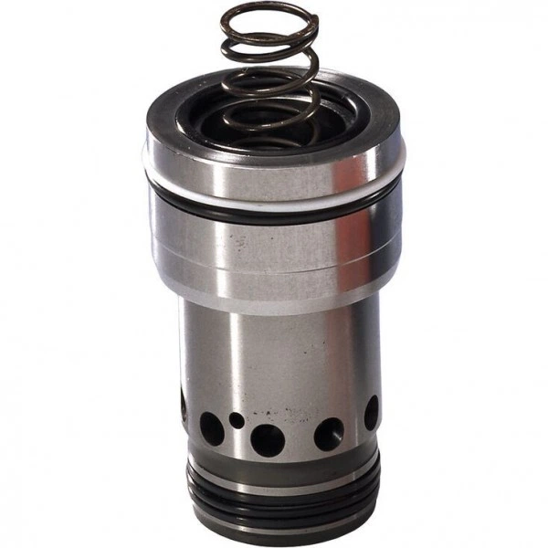
Артикул: RX7315
В наличии
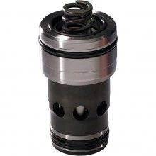
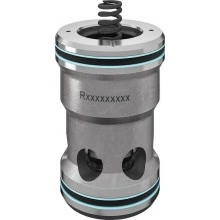
2-way cartridge valves, pressure functions LC..DR (cartridge valves)
Цена по запросу Стоимость зависит от выбранного способа оплаты и количества товара.
Не отвечаем 5 минут — скидка на весь заказ!
Нужна скидка? Звони — сделаем лучшее предложение
Работаем по всей России
Возможны самовывоз и доставка по всей территории России
Надежность
Профессиональная поддержка
Description
- Size 16 … 63
- Maximum flow 1600 l/min
- Size 16 … 63
Product description
General
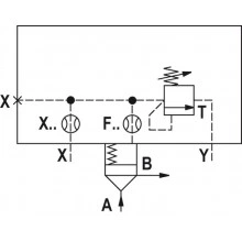
2-way cartridge valves for pressure functions are pilot-operated valves in seat or spool design. The power section designed as cartridge valve (1) is installed into a receiving hole standardized according to DIN ISO 7368 and closed with a control cover (2).
The pilot control valve (4) for manual or electrically proportional pressure adjustment is integrated into the control cover (2) or is installed on the control cover (2) as pilot valve with mounting dimensions according to DIN 24 340.
By combination of cartridge valves with the control covers, different pressure functions can be realized. .
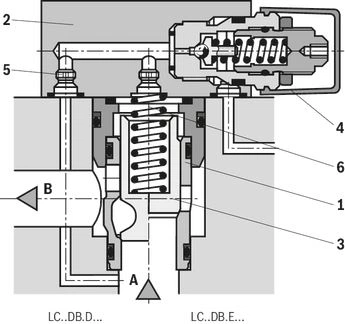
Pressure reducing function
Rest position open
The cartridge valve for the pressure reducing function is designed as spool valve without area difference (no effective areas at port B).
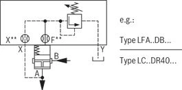
As pilot control valve, identical cover types as for the pressure relief function are applied (type LFA..DB...).
The effective pressure at port A is directed via the pilot oil supply orifice to the spring side of the spool. Under the performance limit and the pressure set at the pilot control valve, the spool is pressure-compensated and retained in open position by the spring force to enable free flow from port B to port A.
On reaching the set pressure, the spool is closed and the pressure at port A is reduced according to the pressure-flow characteristics.
Type code
| Type | ||
| 01 | Cartridge valve | LC |
| Size | ||
| 02 | NG 16 | 16 |
| NG 25 | 25 | |
| NG 32 | 32 | |
| NG 40 | 40 | |
| NG 50 | 50 | |
| NG 63 | 63 | |
| Version | ||
| 03 | Pressure relief function | DR |
| Cracking pressure | ||
| 04 | Cracking pressure 0 bar (without spring) | 00 |
| Cracking pressure approx. 2 bar | 20 | |
| Cracking pressure approx. 3 bar 1) | 30 | |
| Cracking pressure approx. 4 bar | 40 | |
| Cracking pressure approx. 5 bar (NG16, 25 and 32 only) | 50 | |
| Cracking pressure approx. 8 bar 2) | 80 | |
| Damping | ||
| 05 | Piston without precision grooves | E |
| Component series | ||
| 06 | Component series 70 ... 79 (70 ... 79: unchanged installation and connection dimensions) | 7X |
| Seal material | ||
| 07 | NBR seals | no code |
| FKM seals | V | |
| 01 | 02 | 03 | 04 | 05 | 06 | 07 | |
| LC | DR | E | 7X | / |
Additional preferred types and standard units are specified in the EPS (standard price list).
Technical data
| Hydraulic fluid | Classification | Suitable sealing materials | Standards | |
| Mineral oil | HL, HLP | FKM, NBR | DIN 51524 | |
| Bio-degradable | Insoluble in water | HEES (synthetic esters) | FKM | VDMA 24568 |
| HETG (rape seed oil) | FKM, NBR | |||
| Soluble in water | HEPG (polyglycols) | FKM | VDMA 24568 | |
| Other hydraulic fluids on request | ||||
hydraulic
| Size | 16 | 25 | 32 | 40 | 50 | 63 | ||
| Maximum operating pressure | Anschluss A | bar | 315 | |||||
| Port B | bar | 315 | ||||||
| Maximum flow | LC..DR20.../.. | l/min | 100 | 200 | 300 | 750 | 1000 | 1600 |
| LC..DR40.../.. | l/min | 150 | 300 | 450 | 1000 | 1300 | 2000 | |
| Hydraulic fluid | Mineral oil (HL, HLP) according to DIN 51524; fast biodegradable hydraulic fluids according to VDMA 24568 ; HETG (rape seed oil); HEPG (polyglycols); HEES (synthetic esters), other hydraulic fluids on request | |||||||
| Hydraulic fluid temperature range | NBR seals | °C | -30 … +80 | |||||
| FKM seals | °C | -20 … +80 | ||||||
| Viscosity range | mm²/s | 2.8 … 380 | ||||||
| Maximum admissible degree of contamination of the hydraulic fluid 1) | Class 20/18/15 according to ISO 4406 (c) | |||||||
| 1) | The cleanliness classes specified for the components must be adhered to in hydraulic systems. Effective filtration prevents faults and simultaneously increases the life cycle of the components. For the selection of the filters, see www.boschrexroth.com/filter. |
(For applications outside these values, please consult us!)
Diagrams/characteristic curves
(measured with HLP46, ϑOil = 40 ±5 °C)
LC 16 DR…

LC 16 DR…

LC 16 DR…

LC 16 DR…
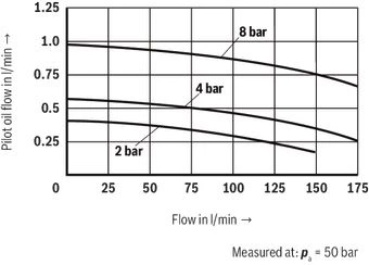
(measured with HLP46, ϑOil = 40 ±5 °C)
LC 25 DR…
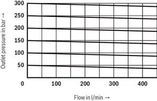
LC 25 DR…

LC 25 DR…

LC 25 DR…
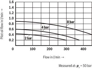
(measured with HLP46, ϑOil = 40 ±5 °C)
LC 32 DR…
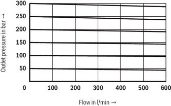
LC 32 DR…

LC 32 DR…

LC 32 DR…
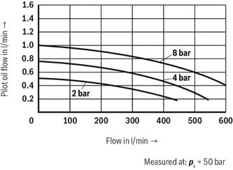
(measured with HLP46, ϑOil = 40 ±5 °C)
LC 40 DR…

LC 40 DR…

LC 40 DR…

LC 40 DR…
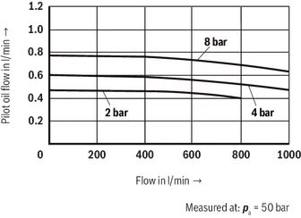
(measured with HLP46, ϑOil = 40 ±5 °C)
LC 50 DR…
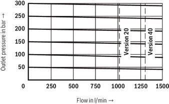
LC 50 DR…

LC 50 DR…

LC 50 DR…
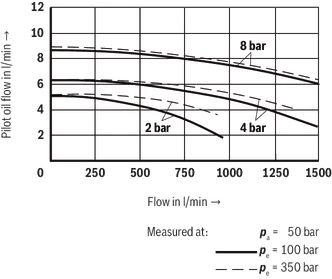
(measured with HLP46, ϑOil = 40 ±5 °C)
LC 63 DR…

LC 63 DR…

LC 63 DR…

LC 63 DR…
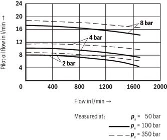
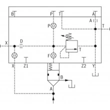
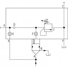
Symbols/Circuit diagrams

| Version "E" | Version “D” | ||
| Area ratio | Area ratio | Area ratio | Area ratio |
Dimensions
Installation bore and connection dimensions according to ISO 7368
Dimensions in mm

| 1 | Depth of fit |
| 2 | Control dimension |
| 3 | If a different diameter is used for port B than ØD3 or (ØD3*), the distance from the cover support surface to the bore center must be calculated. |
| 4 | Port B may be positioned around the central axis of port A. However, it must be observed that the mounting bores and the control bores are not damaged. |
| 7 | At Ø ≤45 mm → Fitting H8 admissible |
| NG | ØD1 | ØD2 | ØD3/(ØD3*) | ØD4 | ØD5 | ØD6 1) | ØD7 | H1/(H1*) | H2 | H3 | H4 | H5 | H6 | H7 | H8 | H9 | L1 | L2 | L3 | L4 | L5 | W | |||
| mm | mm | mm | mm | mm | mm | mm | mm | mm | mm | mm | mm | mm | mm | mm | mm | mm | mm | mm | mm | ||||||
| 16 | 32 | H7 - | 16 | 16 25 | 25 | H7 - | M8 | 8 | 4 | H13 - | 35 29.5 | 56 | 43 | 20 | 11 | 2 | 20 | 2 | 0.5 | 65 80 | 46 | 23 | 25 | 10.5 | 0.05 |
| 25 | 45 | H7 - | 25 | 25 32 | 34 | H7 - | M12 | 6 | 6 | H13 - | 44 40.5 | 72 | 58 | 25 | 12 | 2.5 | 30 | 2.5 | 1 | 85 - | 58 | 29 | 33 | 16 | 0.05 |
| 32 | 60 | H7 - | 32 | 32 40 | 45 | H7 - | M16 | 8 | 6 | H13 - | 52 48 | 85 | 70 | 35 | 13 | 2.5 | 30 | 2.5 | 1.5 | 102 - | 70 | 35 | 41 | 17 | 0.1 |
| 40 | 75 | H7 - | 40 | 40 50 | 55 | H7 - | M20 | 10 | 6 | H13 - | 64 59 | 105 | 87 | 45 | 15 | 3 | 30 | 3 | 2.5 | 125 - | 85 | 42.5 | 50 | 23 | 0.1 |
| 50 | 90 | H7 - | 50 | 50 63 | 68 | H7 - | M20 | 10 | 8 | H13 - | 72 65.5 | 122 | 100 | 45 | 17 | 3 | 35 | 4 | 2.5 | 140 - | 100 | 50 | 58 | 30 | 0.1 |
| 63 | 120 | H7 - | 63 | 63 80 | 90 | H7 - | M30 | 12 | 8 | H13 - | 95 86.5 | 155 | 130 | 65 | 20 | 4 | 40 | 4 | 3 | 180 - | 125 | 62.5 | 75 | 38 | 0.2 |
| 1) | Maximum dimension |
Downloads
 | 2-way cartridge valves, pressure functions Data Sheet | RE21050 | 2003-02-01 | English | PDF | 893k Product Groups: Logic elements - pressure function Type LC (cartridge valves), type LFA (control cover) |
Отзывы о товаре
Аналогичные товары

Официальный поставщик Bosch Rexroth
Продажи на территории России
Оптовые и розничные продажи
Снижение логистических расходов
Индивидуальные условия
Выгода без посредников
Единая система поставок
Весь ассортимент на складе