
Артикул: RX7313
В наличии
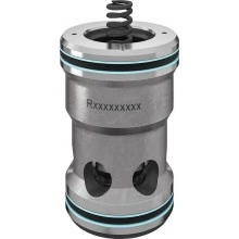
2-way cartridge valves, pressure functions LC..DB (high-pressure)
Цена по запросу Стоимость зависит от выбранного способа оплаты и количества товара.
Не отвечаем 5 минут — скидка на весь заказ!
Нужна скидка? Звони — сделаем лучшее предложение
Работаем по всей России
Возможны самовывоз и доставка по всей территории России
Надежность
Профессиональная поддержка
Description
Features
- Cartridge valves for pressure function
Product description
General
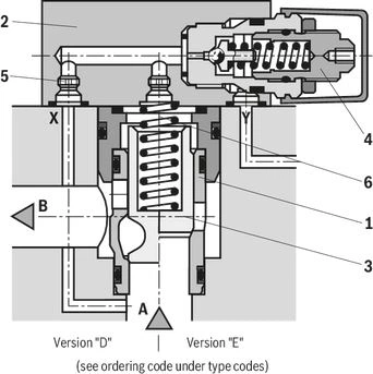
2-way cartridge valves for pressure functions are pilotoperated valves in seat or spool design. The power section designed as cartridge valve (1) is installed into a receiving hole standardized according to ISO 7368 and closed with a control cover (2).
The pilot control valve (4) for manual or electrically proportional pressure adjustment is integrated into the control cover (2) or is installed on the control cover (2).
By combination of cartridge valves with the control covers, different pressure functions can be realized.
Pressure limiting function
The cartridge valve (1) for the pressure relief function (type LC . DB...) is designed as seat valve without area difference (no effective area at port B). The effective pressure at port A is directed via the pilot oil supply orifice (5) to the spring side (6) of the element. Under the pressure set at the pilot control valve (4), the spool (3) is pressure-compensated and closed by the spring force. On reaching the set pressure, the spool (3) is opened and the pressure at port A is limited according to the pressure-flow characteristics.
Type code
| 01 | 02 | 03 | 04 | 05 | 06 | 07 | 08 | |
| LC | DB | / | 450 | P |
| Type | ||
| 01 | Cartridge valve | LC |
| Size | ||
| 02 | Size 16 | 16 |
| Size 25 | 25 | |
| Size 32 | 32 | |
| Size 40 | 40 | |
| Size 50 | 50 | |
| Size 63 | 63 | |
| Size 80 | 80 | |
| Size 100 | 100 | |
| Version | ||
| 03 | Pressure relief function | DB |
| Cracking pressure | ||
| 04 | 0 bar (without spring) | 00 |
| approx. 2 bar | 20 | |
| approx. 4 bar | 40 | |
| approx. 5 bar (NG16, 25 and 32 only) | 50 | |
| approx. 8 bar | 80 | |
| Damping | ||
| 05 | Seat piston without orifice (standard version) | E |
| Seat spool with orifice (orifice Ø see table below) | A | |
| Seat/sliding spool without orifice (standard version) | D | |
| Seat/sliding spool with orifice (orifice Ø see table below) | B | |
| Component series | ||
| 06 | Component series 70 ... 79 (70 ... 79: unchanged installation and connection dimensions) 1) | 7X |
| Component series 60 … 69 (60 … 69: unchanged installation and connection dimensions) 2) | 6X | |
| Series | ||
| 07 | High-pressure series | 450 |
| Seal material | ||
| 08 | H-ECOPUR | P |
| Observe compatibility of seals with hydraulic fluid used. (Other seals upon request) | ||
| 1) Component series 7X for sizes 16...63 | |
| 2) Component series 6X for sizes 80 and 100 |
| Size | Nozzle Ø in mm |
| 16 | 0,7 |
| 25 | 0,8 |
| 32, 40 | 1,0 |
| 50 | 1,2 (seat spool) / 1,5 (seat/sliding spool) |
| 60 | 1,8 |
| 80, 100 | 2,8 |
Technical data
| Hydraulic fluid | Classification | Suitable sealing materials | Standards | Data sheet | |
| Mineral oils | HL, HLP | H-ECOPUR | DIN 51524 | 90220 | |
| Bio-degradable | Insoluble in water | HETG | H-ECOPUR | ISO 15380 | 90221 |
| HEES | H-ECOPUR | ||||
| Flame-resistant | Water-free | HFDU (glycol base) | H-ECOPUR | ISO 12922 | 90222 |
| HFDU (ester base) | H-ECOPUR | ||||
| Important information on hydraulic fluids:
Bio-degradable and flame-resistant: If this hydraulic fluid is used, small amounts of dissolved zinc may get into the hydraulic system. | |||||
(For applications outside these values, please consult us!)
Diagrams/characteristic curves
(simulated with HLP46, ϑoil = 40±5 °C)
Notice:
The characteristic curves were measured with external, depressurized pilot oil return.
Due to the internal pilot oil return, the inlet pressure increases by the output pressure present in port B.
Notice:
The characteristic curves were measured with external, depressurized pilot oil return.
Due to the internal pilot oil return, the inlet pressure increases by the output pressure present in port B.
Notice:
The characteristic curves were measured with external, depressurized pilot oil return.
Due to the internal pilot oil return, the inlet pressure increases by the output pressure present in port B.
Notice:
The characteristic curves were measured with external, depressurized pilot oil return.
Due to the internal pilot oil return, the inlet pressure increases by the output pressure present in port B.
Notice:
The characteristic curves were measured with external, depressurized pilot oil return.
Due to the internal pilot oil return, the inlet pressure increases by the output pressure present in port B.
Notice:
The characteristic curves were measured with external, depressurized pilot oil return.
Due to the internal pilot oil return, the inlet pressure increases by the output pressure present in port B.
Notice:
The characteristic curves were measured with external, depressurized pilot oil return.
Due to the internal pilot oil return, the inlet pressure increases by the output pressure present in port B.
Notice:
The characteristic curves were measured with external, depressurized pilot oil return.
Due to the internal pilot oil return, the inlet pressure increases by the output pressure present in port B.
Notice:
The characteristic curves were measured with external, depressurized pilot oil return.
Due to the internal pilot oil return, the inlet pressure increases by the output pressure present in port B.
Notice:
The characteristic curves were measured with external, depressurized pilot oil return.
Due to the internal pilot oil return, the inlet pressure increases by the output pressure present in port B.
Notice:
The characteristic curves were measured with external, depressurized pilot oil return.
Due to the internal pilot oil return, the inlet pressure increases by the output pressure present in port B.
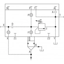
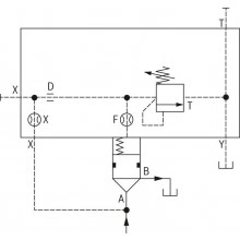
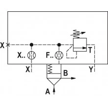
Symbols/Circuit diagrams
| Version "E" | Version "A" | Version “D” | Version "B" |
 |  |  |  |
Dimensions
Installation bore according to ISO 7368
Dimensions in mm
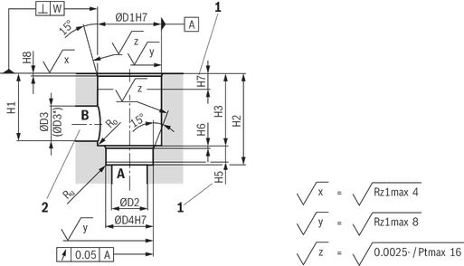
| 1 | Depth of fit |
| 2 | Port B may be positioned around the central axis of port A. However, it must be observed that the mounting bores and the control bores are not damaged. |
Downloads
 | 2-way cartridge valves, pressure functions Data Sheet | RE21050 | 2003-02-01 | English | PDF | 893k Product Groups: Logic elements - pressure function Type LC (cartridge valves), type LFA (control cover) |
Отзывы о товаре
Аналогичные товары
Официальный поставщик Bosch Rexroth
Продажи на территории России
Оптовые и розничные продажи
Снижение логистических расходов
Индивидуальные условия
Выгода без посредников
Единая система поставок
Весь ассортимент на складе