")
Артикул: RX7290
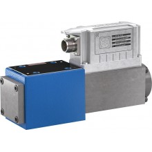
2-way cartridge valves, directional functions LFA..WEMB (high-pressure)
Доступно к заказу
Цена по запросу
И выбери подходящего.
Description
Features
- Control cover for directional function
Product description
2-way cartridge valves are elements that have been designed for a compact block design. The power section with connections A and B is installed into the control block in a receiving hole standardized according to ISO 7368 and closed with a cover. In most cases, the cover is simultaneously the connection from the control side of the power section to the pilot control valves. By control with respective pilot control valves, the power section can be applied for pressure, directional and throttle functions or a combination of these functions. Particularly efficient solutions are realized by adjustment of the size to various flows of the individual ways of an actuator. The application of power sections of elements for multiple functions is very cost-effective.
2-way cartridge valves generally consist of control cover (1) and installation kit (2). The control cover contains the control bores and optionally a stroke limitation function, a hydraulically controlled directional seat valve or a shuttle valve according to the required overall function. Additionally, electrically operated directional spool or seat valves can be installed at a control cover. The installation kit consists of a bushing (3), ring (4) (only up to NG32), valve poppet (5), optionally with damping nose (6) or without damping nose (7) as well as closing spring (8).
The function of 2-way cartridge valves is pressuredependent. This way, three crucial pressurized areas A1, A2, A3 are realized for the function. The area at the valve seat A1 is considered as 100 %. Depending on the version, the annulus area A2 realized by grading is 7 % or 50 % of area A1. The area ratio A1 : A2 is respectively either 14.3 : 1 or 2 : 1. The area A3 is identical to the sum of areas A1 + A2. Due to the different area ratios A1 : A2 and the resulting different annulus areas (A2), the area A3 is one time 107 % and another time 150 % of the area A1 at the seat, which is observed as 100 %.
In general, the following applies:
The areas A1 and A2 are effective in opening direction. The area A3 and the spring are effective in closing direction. The direction of action of the resulting force from the opening and closing forces determines the spool position of the 2-way cartridge valve.
The 2-way cartridge valves can be passed from A to B or from B to A. In case of pressurization of area A3 by pilot oil discharge from channel B or external pilot oil supply, channel A is blocked in a leakage-free manner.


Type code
| 01 | 02 | 03 | 04 | 05 | 06 | 07 | 08 | ||
| LFA | WEMB | – | / | 450 |
| Type | ||
| 01 | Control cover LFA | LFA |
| Size | ||
| 02 | NG 16 | 16 |
| NG 25 | 25 | |
| NG 32 | 32 | |
| NG 40 | 40 | |
| NG 50 | 50 | |
| NG 63 | 63 | |
| NG 80 | 80 | |
| NG 100 | 100 | |
| Version | ||
| 03 | Control cover version "WEMB": For set-up of a directional valve | WEMB |
| Component series | ||
| 04 | Component series 70 ... 79 (70 ... 79: unchanged installation and connection dimensions) 1) | 7X |
| Component series 60 … 69 (60 … 69: unchanged installation and connection dimensions) 2) | 6X | |
| Series | ||
| 05 | High-pressure series | 450 |
| Nozzle fitting | ||
| 06 | Orifice in channel P 3) | P.. |
| 07 | Orifice in channel T 3) | T.. |
| 08 | Orifice in channel F 3) | F.. |
| 1) Component series 7X for sizes 16...63 | |
| 2) Component series 6X for sizes 80 and 100 | |
| 3) This orifice is designed as screw-type orifice. If an orifice is to be installed, the respective code letter with the orifice Ø in 1/10 mm has to be entered in the type designation. | |
| Example: P12 = Orifice with Ø1.2 mm in channel P. Additional orifice Ø see diagrams/characteristic curves. |
| Orifice symbol | Symbol in ordering code | |||
| A** |  | A** |  | This orifice is designed as screw-type orifice. If an orifice is to be installed, the respective code letter with the orifice Ø in 1/10 mm has to be entered in the type designation. Example: A12 = Orifice with Ø1.2 mm in channel A. |
| Ø1,2 |  |  | This orifice is designed as bore. No specifications are made in the type designation. (Orifice Ø in mm) | |
| Z12 |  |  | This orifice is designed as screw-type orifice. This is a standard orifice. No specifications are made in the type designation. (Orifice Ø in 1/10 mm) | |
Notices:
- For ordering code of orifices, see "Accessories"
- Additional functions with special numbers see "Information".
Technical data
load errorDiagrams/characteristic curves
load errorDimensions
load errorInformation
load errorDownloads
| 2-way cartridge valves, directional functions Data Sheet | RE21010 | 2017-05-01 | English | PDF | 3.2MB Product Groups: Logic elements - directional function Type LC (cartridge valves), type LFA (control cover) |

Нет отзывов об этом товаре.