
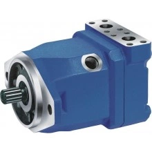
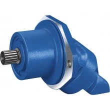
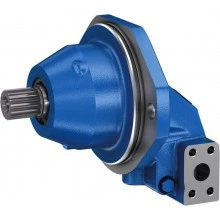
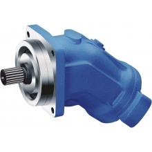
Инновационные решения Bosch Rexroth: соблюдение жёстких норм выбросов и увеличение надёжности производства
Компания Bosch Rexroth является одним из ведущих производителей компонентов и систем гидравлики и электроприводов. Её пр...
Читать далее →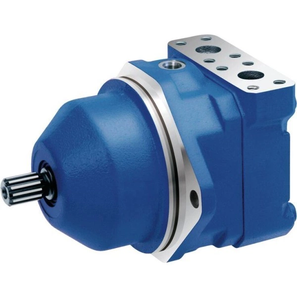
Артикул: RX7208
В наличии
Цена по запросу Стоимость зависит от выбранного способа оплаты и количества товара.
Не отвечаем 5 минут — скидка на весь заказ!
Нужна скидка? Звони — сделаем лучшее предложение
Работаем по всей России
Возможны самовывоз и доставка по всей территории России
Надежность
Профессиональная поддержка
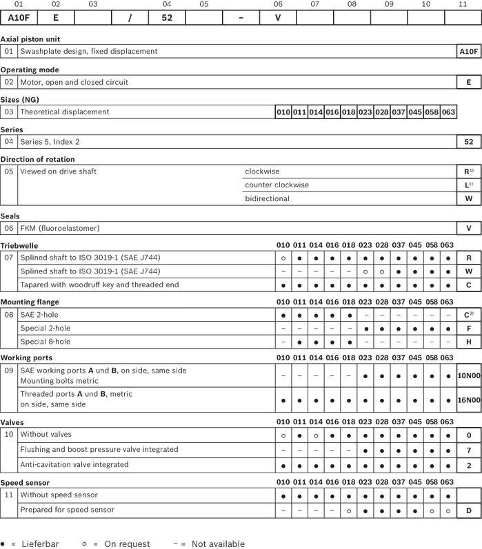
| 1) | Only necessary in conjunction with valve configuration "2" (integrated anti cavitation valve) |
| 2) | Drive shaft R with flange C on sizes 10 … 18 in preparation |
| Size | 10 | 11 | 14 | 16 | 18 | 23 | 28 | 37 | 45 | 58 | 63 | |||
| Displacement | Vg | cm³ | 10.6 | 11.5 | 14.1 | 16.1 | 18 | 23.5 | 28.5 | 36.7 | 44.5 | 58 | 63.1 | |
| Nominal pressure | pnom | bar | 280 | 280 | 280 | 280 | 280 | 280 | 280 | 280 | 280 | 280 | 280 | |
| Maximum pressure | pmax | bar | 350 | 350 | 350 | 350 | 350 | 350 | 350 | 350 | 350 | 350 | 350 | |
| Maximum speed 1) | nnom | rpm | 5000 | 4200 | 4200 | 4200 | 4200 | 4900 | 4700 | 4200 | 4000 | 3600 | 3400 | |
| Inlet flow | at nnom | qV | l/min | 53 | 48 | 59 | 68 | 76 | 115 | 134 | 154 | 178 | 209 | 215 |
| Power | at nnom and pnom | P | kW | 24.7 | 22.5 | 27.6 | 31.6 | 35.3 | 53.6 | 62.5 | 71.8 | 83.1 | 97.4 | 100.1 |
| Starting torque | at nnom and pnom | M0 | Nm | 37.5 | 30 | 45 | 53 | 67.5 | 75 | 105 | 125 | 170 | 205 | 230 |
| Torque | at pnom | M | Nm | 47 | 51 | 63 | 72 | 80 | 105 | 127 | 163 | 198 | 258 | 281 |
| Rotary stiffness | Drive shaft R | c | kNm/rad | 14.835 | 28.478 | 28.478 | 46.859 | 46.859 | 80.59 | 80.59 | ||||
| Drive shaft W | c | kNm/rad | 38.489 | 34.489 | 60.907 | 60.907 | ||||||||
| Drive shaft C | c | kNm/rad | 15.084 | 18.662 | 18.662 | 18.662 | 18.662 | 30.017 | 30.017 | 46.546 | 46.546 | 87.667 | 87.667 | |
| Moment of inertia for rotary group | JTW | kg·m² | 0.0006 | 0.00093 | 0.00093 | 0.00093 | 0.00093 | 0.0017 | 0.0017 | 0.0033 | 0.0033 | 0.0056 | 0.0056 | |
| Maximum angular acceleration | ɑ | rad/s² | 8000 | 6800 | 6800 | 6800 | 6800 | 5500 | 5500 | 4000 | 4000 | 3300 | 3300 | |
| Case volume | V | l | 0.1 | 0.15 | 0.15 | 0.15 | 0.15 | 0.6 | 0.6 | 0.7 | 0.7 | 0.8 | 0.8 | |
| Weight (approx.) | m | kg | 5 | 6.5 | 6.5 | 6.5 | 6.5 | 12 | 12 | 17 | 17 | 22 | 22 | |
| 1) | At least 18 bar required at low pressure side |
| Determining the operating characteristics | ||
| Inlet flow |  | [l/min] |
| Rotational speed |  | [rpm] |
| Torque |  | [Nm] |
| Power |  | [kW] |
| Key | |
| Vg | Displacement per revolution [cm3] |
| Δp | Differential pressure [bar] |
| n | Rotational speed [rpm] |
| ηv | Volumetric efficiency |
| ηhm | Hydraulic-mechanical efficiency |
| ηt | Total efficiency (ηt = ηv • ηhm) |
The axial piston unit is designed for operation with mineral oil HLP according to DIN 51524.
Application instructions and requirements for hydraulic fluids should be taken from the following data sheets before the start of project planning:
For operation with environmentally acceptable fluids please consult us.
|
| Viscosity | Shaft | Temperature1) | Comment |
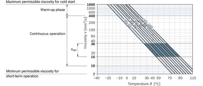
| Cold start | νmax ≤ 1600 mm²/s | NBR2) | ϑSt ≥ -40 °C | t ≤ 1 min, without load (p ≤ 30 bar), n ≤ 1000 rpm, |
| FKM | ϑSt ≥ -25 °C | |||
| Warm-up phase | ν = 400 … 1600 mm²/s |
| t ≤ 15 min, p ≤ 0.7 • pnom and n ≤ 0.5 • nnom | |
| Continuous operation | ν = 10 … 400 mm²/s3) | NBR2) | ϑ ≤ +78 °C | measured at port L |
| FKM | ϑ ≤ +103 °C | |||
| νopt = 16 … 36 mm²/s | range of optimum operating viscosity and efficiency | |||
| Short-term operation | νmin = 7 … 10 mm²/s | NBR2) | ϑ ≤ +78 °C | t ≤ 3 min, p ≤ 0.3 • pnom measured at port L |
| FKM | ϑ ≤ +103 °C |
| 1) | If the specified temperatures cannot be maintained due to extreme operating parameters, please contact us. |
| 2) | Special version, please contact us. |
| 3) | Equates e.g. with the VG 46 a temperature range of +5 °C to +85 °C (see selection diagram) |
Bosch Rexroth evaluates hydraulic fluids on the basis of the Fluid Rating according to the technical data sheet 90235.
Hydraulic fluids with positive evaluation in the Fluid Rating are provided in the following technical data sheet:
The hydraulic fluid should be selected so that the operating viscosity in the operating temperature range is within the optimum range (νopt; see selection diagram).
Finer filtration improves the cleanliness level of the hydraulic fluid, which increases the service life of the axial piston unit.
A cleanliness level of at least 20/18/15 is to be maintained according to ISO 4406.
At a hydraulic fluid viscosity of less than 10 mm²/s (e.g. due to high temperatures in short-term operation) at the drain port, a cleanliness level of at least 19/17/14 according to ISO 4406 is required.
For example, the viscosity is 10 mm²/s at:
| Pressure at working port A or B | Definition | ||
| Nominal pressure | pnom | see table of values | The nominal pressure corresponds to the maximum design pressure. |
| Maximum pressure | pmax | see table of values | The maximum pressure corresponds to the maximum operating pressure within the single operating period. The sum of the single operating periods must not exceed the total operating period. |
| Single operating period | 2.5 s | ||
| Total operating period | 300 h | ||
| Minimum pressure (high-pressure side) | pHP min | 10 bar | Minimum pressure on high- or low-pressure side (port A or B) required to prevent damage to the axial piston unit. |
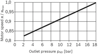
| Minimum pressure (low-pressure side) | pLP min | see diagram "Permissible rotational speed in relation to outlet pressure" | |
| Rate of pressure change | Definition | ||
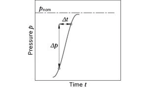
| Rate of pressure change | RA max | 16000 bar/s | Maximum permissible rate of pressure build-up and reduction during a pressure change over the entire pressure range. |
| Case pressure at port L | Definition | ||
| Motor operation mode | pL max | 4 bar absolute | Maximum permissible case pressure measured at port L or L1 |
| Pump operating mode | pL max | 2 bar absolute | |
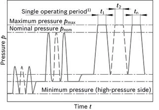
| 1) | Total operating period = t1 + t2 + ... + tn |
| Direction of rotation, viewed on drive shaft | |
| clockwise | counter-clockwise |
| A to B | B to A |
| Size | 10 | 11 | 14 | 16 | 18 | 23 | 28 | 37 | 45 | 58 | 63 | ||||
| Splined shaft | Code | R | R | R | R | R | R, W | R, W | R, W | R, W | R, W | R, W | |||
| Tapered shaft | Code | C | C | C | C | C | C | C | C | C | C | C | |||
| Maximum radial force |  |  | Fq max | N | 250 | 350 | 350 | 350 | 350 | 1200 | 1200 | 1500 | 1500 | 1700 | 1700 |
| Maximum axial force |  | ± Fax max | N | 400 | 700 | 700 | 700 | 700 | 1000 | 1000 | 1500 | 1500 | 2000 | 2000 | |
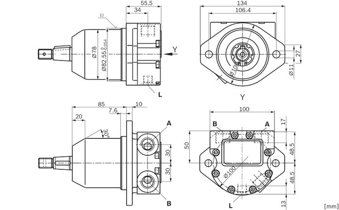
| 1) | Flange ISO 3019-1 |
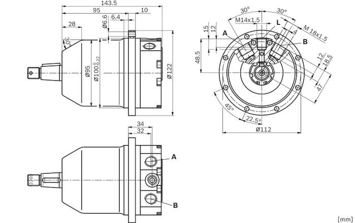
| Size | 10 | ||
| A, B | Working port | Size | M18 × 15; 17 mm deep |
| Standard | DIN 3852 | ||
| State on delivery | With protective cover (must be connected) | ||
| L | Drain port | Size | M14 × 15; 13 mm deep |
| Standard | DIN 3852 | ||
| State on delivery | With protective cover (must be connected) | ||
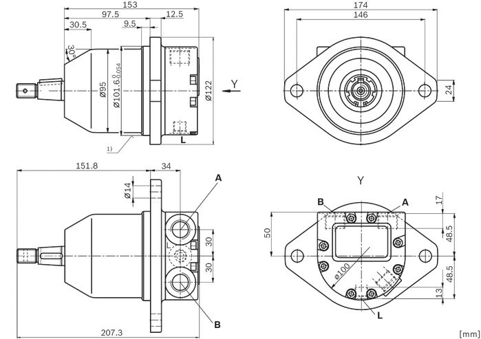
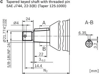
| 1) | Flange ISO 3019-1 |
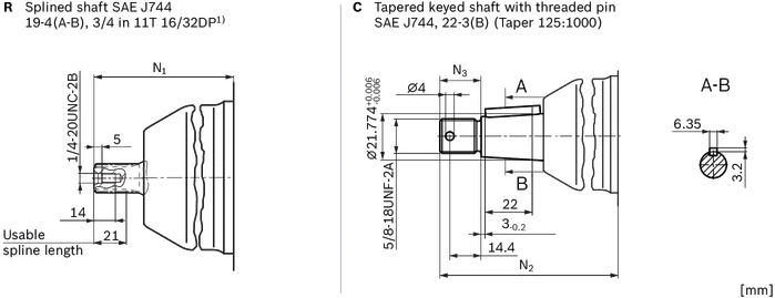
| 1) | Involute spline according to ANSI B92.1a, 30° pressure angle, flat root, side fit, tolerance class 5 |
| Mounting flange | N1 | N2 | N3 |
| H | 126.6 | 144.2 | 19 |
| C | ‒ | 151.8 | 24 |
| Size | 11 | 14 | 16 | 18 | ||
| A, B | Working port | Size | M18 × 15; 12 mm deep | |||
| Standard | DIN 3852 | |||||
| State on delivery | With protective cover (must be connected) | |||||
| L | Drain port | Size | M14 × 15; 12 mm deep | |||
| Standard | DIN 3852 | |||||
| State on delivery 1) | With protective cover (observe installation instructions) | |||||
| L1 | Drain port | Size | M14 × 15; 12 mm deep | |||
| Standard | DIN 3852 | |||||
| State on delivery 1) | Plugged (observe installation instructions) | |||||
| 1) | Unless otherwise specified. Other layouts on request. |
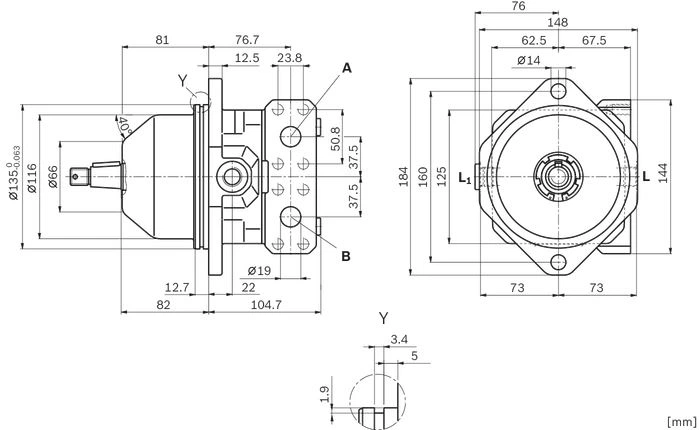
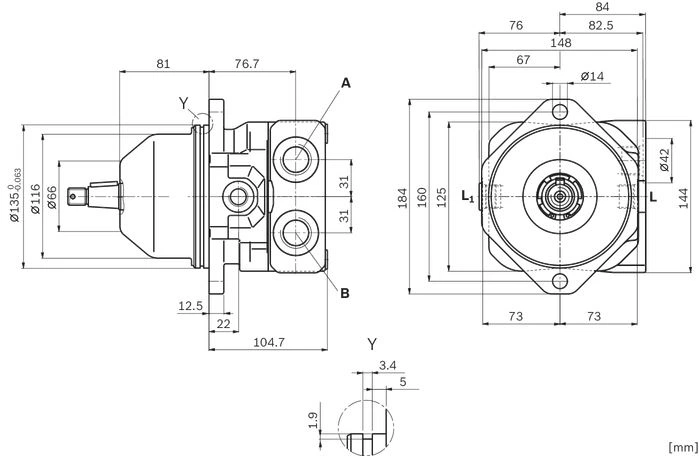
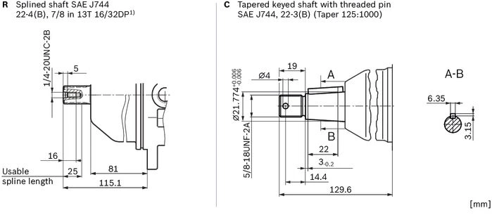
| 1) | Involute spline according to ANSI B92.1a, 30° pressure angle, flat root, side fit, tolerance class 5 |
| Size | 23 | 28 | ||
| A, B | Working port | Size | 3/4 in | |
| Standard | Dimensions according to SAE J518 | |||
| Fastening thread 1) | M10 × 15; 17 mm deep | |||
| State on delivery | With protective cover (must be connected) | |||
| A, B | Working port | Size | M27 × 2; 16 mm deep | |
| Standard | DIN 3852 | |||
| State on delivery | With protective cover (must be connected) | |||
| L | Drain port | Size | 3/4-16 UNF-2B; 11 mm deep | |
| Standard 2) | ISO 11926 | |||
| State on delivery 3) | With protective cover (observe installation instructions) | |||
| L1 | Drain port | Size | 3/4-16 UNF-2B; 11 mm deep | |
| Standard 2) | ISO 11926 | |||
| State on delivery 3) | Plugged (observe installation instructions) | |||
| 1) | Thread according to DIN 13 |
| 2) | The spot face can be deeper than specified in the appropriate standard. |
| 3) | Unless otherwise specified. Other layouts on request. |
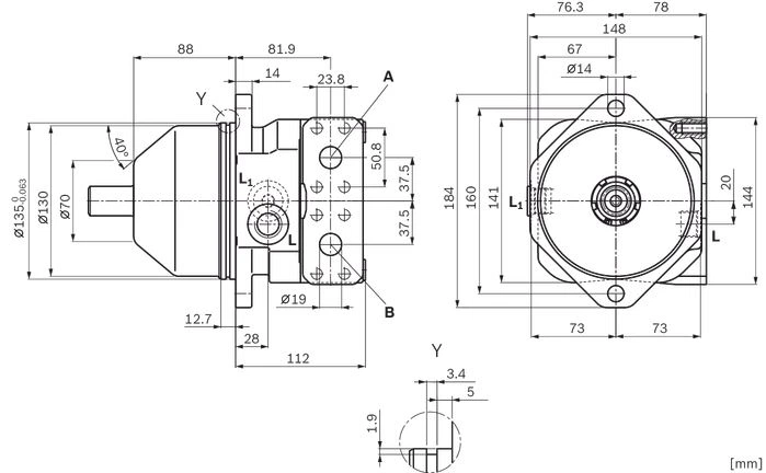
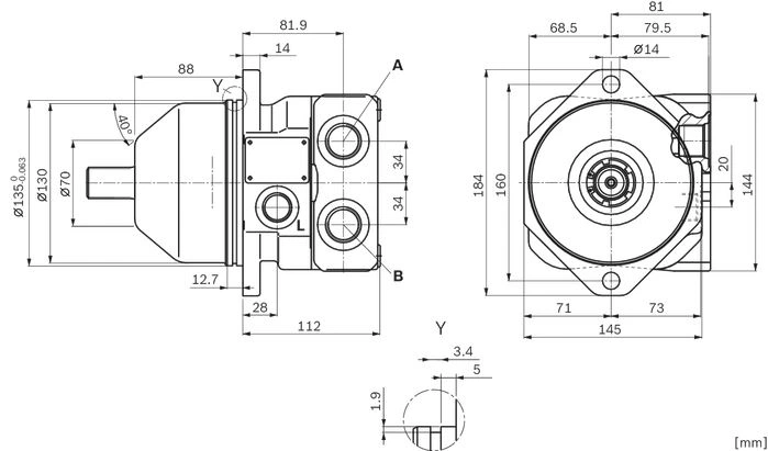
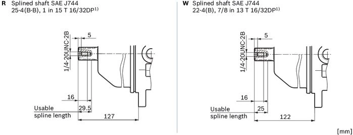
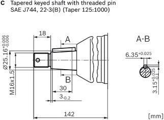
| 1) | Involute spline according to ANSI B92.1a, 30° pressure angle, flat root, side fit, tolerance class 5 |
| Size | 37 | 45 | ||
| A, B | Working port | Size | 3/4 in | |
| Standard | Dimensions according to SAE J518 | |||
| Fastening thread 1) | M10 × 15; 17 mm deep | |||
| State on delivery | With protective cover (must be connected) | |||
| A, B | Working port | Size | M27 × 2; 16 mm deep | |
| Standard | DIN 3852 | |||
| State on delivery | With protective cover (must be connected) | |||
| L | Drain port | Size | 7/8-14 UNF-2B; 13 mm deep | |
| Standard 2) | ISO 11926 | |||
| State on delivery 3) | With protective cover (observe installation instructions) | |||
| L1 | Drain port | Size | 7/8-14 UNF-2B; 13 mm deep | |
| Standard 2) | ISO 11926 | |||
| State on delivery 3) | Plugged (observe installation instructions) | |||
| 1) | Thread according to DIN 13 |
| 2) | The spot face can be deeper than specified in the appropriate standard. |
| 3) | Unless otherwise specified. Other layouts on request. |
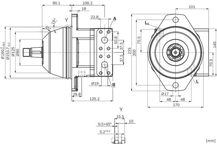
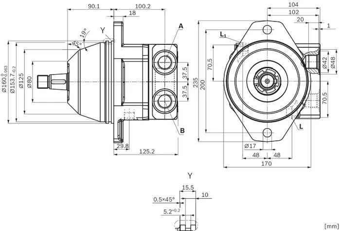
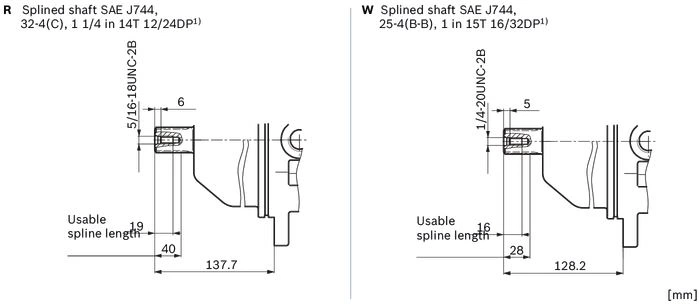
| 1) | Involute spline according to ANSI B92.1a, 30° pressure angle, flat root, side fit, tolerance class 5 |
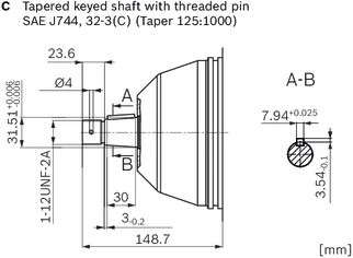
| Size | 58 | 63 | ||
| A, B | Working port | Size | 3/4 in | |
| Standard | Dimensions according to SAE J518 | |||
| Fastening thread 1) | M10 × 15; 17 mm deep | |||
| State on delivery | With protective cover (must be connected) | |||
| A, B | Working port | Size | M27 × 2; 16 mm deep | |
| Standard | DIN 3852 | |||
| State on delivery | With protective cover (must be connected) | |||
| L | Drain port | Size | 7/8-14 UNF-2B; 13 mm deep | |
| Standard 2) | ISO 11926 | |||
| State on delivery 3) | With protective cover (observe installation instructions) | |||
| L1 | Drain port | Size | 7/8-14 UNF-2B; 13 mm deep | |
| Standard 2) | ISO 11926 | |||
| State on delivery 3) | Plugged (observe installation instructions) | |||
| 1) | Thread according to DIN 13 |
| 2) | The spot face can be deeper than specified in the appropriate standard. |
| 3) | Unless otherwise specified. Other layouts on request. |
The flushing and boost pressure valve is used in closed circuits for the removal of heat and to ensure a minimum boost pressure level.
Hydraulic fluid is directed from the respective low pressure side into the motor housing. This is then fed into the reservoir, together with the leakage. The removed hydraulic fluid must be replaced by cooled hydraulic fluid from the boost pump.
The valve is integrated into the port plate.
Cracking pressure of pressure retaining valve
(observe when setting the primary valve)
Fixed setting: 16 bar
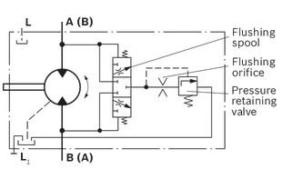
Orifices can be used to set the flushing flows as required.
The specifications below are based on:
ΔpND = pND – pG = 20 bar and ν = 10 mm²/s
(pND = low pressure, pG = case pressure)
Standard flushing flow is 5.5 l/min with orifice ⌀1.6 mm. Other orifice diameters are available, please state in clear text when ordering.
| Flushing flow qv | Orifice-⌀ |
| l/min | mm |
| 3.5 | 1.2 |
| 5.5 | 1.6 |
| 9 | 2 |
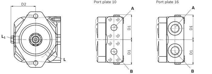
| Size | D1 | D2 |
| mm | mm | |
| 23, 28 | 72 | 72 |
| 37, 45 | 77 | 77 |
| 58, 63 | 77 | 82 |
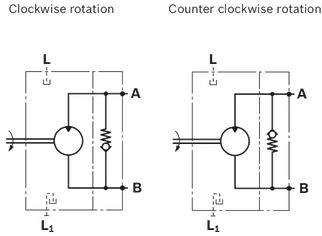
When stopping a system with a relatively large mass (i.e. fan drive) the anti-cavitation valve provides fluid to the motor inlet during the coasting time.
The valve is integrated into the port plate.
Please note:
Then direction of rotation must be fixed to clockwise or counter clockwise during project planning.
The outside dimensions of the motor with anti-cavitation valve are identical to the standard version.
(except A10FE, size 11 … 18, with 8-hole mounting flange)
The version A10F...D ("Prepared for speed sensor", i.e. without sensor) is equipped with an extra port D for installation of a suitable sensor and with a toothed ring on the rotary group. The toothing can be scanned by a sensor and a speed-proportional signal can thus be generated.
On deliveries the sensor port D is plugged with a pressure-resistant cover.
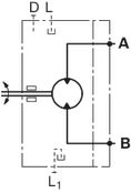
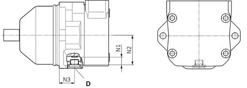
| Motor | Number of teeth | N1 | N2 | N3 | Thread |
| Size | mm | mm | mm | D | |
| 23, 28 | 48 | 20.7 | 65.7 | 27.7 | M18 × 15 |
| 37, 45 | 48 | 17 | 66 | 33.9 | |
| 58, 63 | 56 | 13.3 | 69 | 46.1 |
See the following examples 1 to 4.
Further installation positions are possible upon request. Recommended installation position: 1 and 2.
Below-tank installation is at hand if the axial piston unit is installed below the minimum liquid level outside the tank.
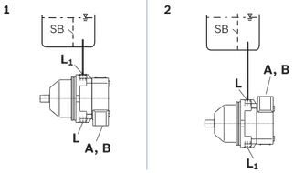
| Installation position | Air bleeding | Filling |
| 1 | ‒ | L1 |
| 2 | ‒ | L |
Above-reservoir installation means that the axial piston unit is installed above the minimum fluid level of the reservoir.
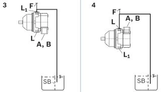
| Installation position | Air bleeding | Filling |
| 3 | F | L1 (F) |
| 4 | F | L (F) |
| Key | |
| F | Filling / Air bleeding |
| L, L2 | Drain port |
| SB | Baffle (baffle plate) |
| A, B | Working port |
Официальный поставщик Bosch Rexroth
Продажи на территории России
Оптовые и розничные продажи
Снижение логистических расходов
Индивидуальные условия
Выгода без посредников
Единая система поставок
Весь ассортимент на складе