
Доступно к заказу
Цена по запросу
И выбери подходящего.
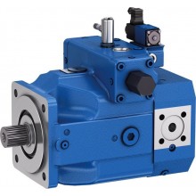
Description
- Frame size 4, 5
- Size 25 … 125
- Component series 4X
- Maximum operating pressure 210 bar
- Maximum displacement 125.3 cm³
Features
- Low operating noise
- Low flow pulsation
- High efficiency also at low viscosity due to sealing gap compensation
- Suitable for broad viscosity and speed ranges
- Use:
For variable speed drives with a large number of load cycles, e. g. plastics processing machines
Product description

Set-up
Hydraulic pumps of type PGM-4X are gap-compensated internal gear pumps with constant displacement. They basically comprise of: Mounting flange (1), housing (2), cover (3), pinion shaft (4), internal gear (5), plain bearings (6), axial washers (7) and stop pin (8), as well as the radial compensation consisting of segment (9), segment support (10) and the seal rolls (11).
Suction and displacement procedure
The hydrodynamically mounted pinion shaft (4) drives the internally geared internal gear (5) in the direction of rotation shown. The tooth clearances opening in the suction range suck in the hydraulic fluids. The hydraulic fluid is transported into the tooth clearances of pinion and internal gear, from the suction range (S) into the pressure range (P). There, the hydraulic fluid is displaced from the closing tooth clearances and delivered into the pressure port (P).
Suction and pressure range are separated by the radial compensation elements (9 to 11) and the tooth engagement between internal gear and pinion shaft.
Axial compensation

The displacement area in the pressure range is axially sealed by axial washers (7). To the sides of the axial washers facing away from the displacement area a pressure field (12) is applied. These fields balance the axial washers vis-à-vis the displacement area, which results in a perfect sealing with low mechanical losses.
Radial compensation

The radial compensation elements consist of segment (9), segment support (10) and seal rolls (11). Segment (9) and segment support (10) are arranged in the pressure field so that the resulting compressive force is basically accepted by the stop pin. A small compressive force component presses segment and segment support onto the tooth tips of pinion shaft and internal gear and in this way provides for the sealing of the pressure range to the suction range with automatic clearance adjustment. This is the prerequisite for constantly high volumetric efficiency during the entire operating time.
The clearance adjustment of segment and segment support is made possible by the seal rolls located inbetween.
Hydrodynamic and hydrostatic mounting
The pinion shaft (4) is accepted by hydrodynamically lubricated radial plain bearings (6). The internal gear (5) is mounted hydrostatically in the housing.
Gear tooth system
The gear tooth system with involute edges has a large meshing length for little flow and pressure pulsation and thus guarantees low-noise running.
Materials used
Flange (1) and cover (3): cast iron
Housing (2) and lateral washers (7): aluminum
Shaft (4) and internal gear (5): steel
Hydraulic pumps of type PGM-4X are gap-compensated internal gear pumps with fixed displacement.
Type code
| 01 | 02 | 03 | 04 | 05 | 06 | 07 | 08 | 09 | 10 | 11 | ||
| PG | M | – | 4X | / | R | 11 | V | U2 |
| Type | |||
| 01 | Internal gear pump, fixed displacement, gap-compensated | PG | |
| Series | |||
| 02 | Medium pressure pump, peak pressure 210 bar | M | |
| Frame sizes BG | |||
| 03 | BG4 | 4 | |
| BG5 | 5 | ||
| Series | |||
| 04 | Series 40 to 49 (40 to 49: unchanged installation and connection dimensions) | 4X | |
| Sizes | NG | ||
| 05 | BG4 | 25 | 025 |
| 32 | 032 | ||
| 40 | 040 | ||
| 50 | 050 | ||
| 63 | 063 | ||
| BG5 | 80 | 080 | |
| 100 | 100 | ||
| 125 | 125 | ||
| Directions of rotation | |||
| 06 | Viewed on drive shaft | right | R |
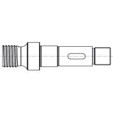
| Drive shafts | |||
| 07 | Parallel keyed shaft, ISO 3019-2 | A | |
| Splined shaft SAE J744 with involute tooth system according to ANSI B92.1a | T | ||
| Line connection | |||
| 08 | Suction and pressure port: SAE J518 | 11 | |
| Seals | |||
| 09 | FKM (fluor-caoutchouc) | V | |
| Mounting flange | |||
| 10 | SAE 2-hole according to SAE J744 | U2 | |
| Additional details | |||
| 11 | Further details in the plain text | ||
Preferred types PGM5-4X
Preferred types PGM4-4X
Technical data
Hydraulic fluid
| Hydraulic fluid | |||
| Permissible hydraulic fluid | Mineral oil (HLP) to DIN 51524-2 | ||
| Operating temperature range | Standard liquid | °C | -10 … +80 |
| Ambient temperature range | °C | -20 … +60 | |
| Viscosity range | mm²/s 1) | 10 … 300 | |
| mm²/s 2) | 10 … 100 | ||
| Admissible start viscosity 3) | mm²/s | 2000 | |
| Maximum admissible degree of contamination of the hydraulic fluid 4) | Class 20/18/15 according to ISO 4406 (c) | ||
| 1) | up to n = 1800 rpm |
| 2) | up to n = 3000 rpm |
| 3) | at n = 400 to 1800 rpm |
| 4) | The cleanliness classes specified for the components must be adhered to in hydraulic systems. Effective filtration prevents faults and simultaneously increases the life cycle of the components. For the selection of the filters, see www.boschrexroth.com/filter. |
| Frame size | 4 | 5 | |||||||||||
| Size |
| 25 | 32 | 40 | 50 | 63 | 80 | 100 | 125 | ||||
| Displacement | geometric | Vg | cm³ | 25.3 | 32.7 | 40.1 | 50.7 | 65.5 | 81.4 | 100.2 | 125.3 | ||
| Drive speed | nmin | rpm | 200 | ||||||||||
| nmax | rpm | 3000 | |||||||||||
| Operating pressure, absolute | Inlet 1) | p | bar | 0.8 ... 2 | |||||||||
| Outlet | continuous | Standard liquid | pN | bar | 175 | ||||||||
| Outlet | intermittent 2) | Standard liquid | pmax | bar | 210 | ||||||||
| Flow 3) | qV | l/min | 36.3 | 46.9 | 57.6 | 72.8 | 94 | 116.9 | 143.8 | 179.8 | |||
| Power consumption | Minimum drive power required 4) | pzu | kW | 1.1 | 1.5 | 2.2 | 3 | 4 | |||||
| Weight | m | kg | 12 | 12.5 | 13.5 | 14 | 14.5 | 36.5 | 38 | 39.5 | |||
| Shaft load | Radial and axial forces (e.g. belt pulley) only after coordination | ||||||||||||
| Mounting type | Flange mounting | ||||||||||||
| 1) | Short-time, during start 0.6 bar |
| 2) | Maximum 10 s, at most 50 % of the duty cycle |
| 3) | at n = 1450 rpm, p = 10 bar, v = 30 mm2/s |
| 4) | at p ≈ 1 bar |
Symbols/Circuit diagrams

Dimensions
Frame size 4
With cylindrical shaft or splined shaft and SAE mounting flange 101‒2
Dimensions in mm

Partial view suction port S

Partial view pressure port P

Cylindrical shaft with fitting key ISO 3019-2
A – G25M
Dimensions in mm

Splined shaft SAE J744
T – 25-4 in 15T 16/32DP
Dimensions in mm

Transport thread and measuring port M
Dimensions in mm
Frame size 5
With cylindrical shaft and SAE mounting flange 152‒2
Dimensions in mm

Partial view suction port S

Partial view pressure port P

Parallel keyed shaft, ISO 3019-2
A – G40N
Dimensions in mm

With splined shaft and SAE mounting flange 127‒2
Dimensions in mm

Partial view suction port S

Partial view pressure port P

Splined shaft SAE J744
T – 38-4 in 17T 12/24DP
Dimensions in mm

Project planning information
Intended use
Internal gear pumps are intended for the set-up of hydraulic drive systems in machine and plant construction. During project planning, the basic principles of the EU Machinery Directive or comparable national regulations outside the EU have to be observed.
They must not be used in potentially explosive environments in accordance with directive 94/9/EC (ATEX).
Technical data
The plant or machine manufacturer must ensure compliance with the admissible technical data and operating conditions. The pump itself does not contain a device to prevent operation outside the admissible data. Operating the pump outside of the admissible technical data is possible to a certain extent, however, this requires the explicit written approval by Bosch Rexroth.
All specified technical performance features are average values and apply with the specified boundary conditions. In case of modifications to the basic conditions (e.g. viscosity), the technical data may change as well. Distribution corresponding to the relevant state-of-the-art is possible.
Hydraulic project planning
Bleeding option for commissioning
For Rexroth internal gear pumps PGM.-4X, a manual or switchable bleeding option for the initial commissioning or any re-commissioning after maintenance and repair works is to be provided. The bleeding point has to be put into the pressure line in front of the first valve or check valve. Bleeding may only be effected with a maximum counter pressure of 0.2 bar.
Examples of bleedings circuits
Switchable bleeding

Manually operated bleeding

Suction line
The line cross-sections have to be rated for the designed flows in a manner that an ideal suction speed of 0.6 to 1.2 m/s is achieved on average. The suction speed must not exceed a maximum value of 2 m/s.
The suction cross-sections at the pump itself are designed for the maximum flow and can therefore only be used as reference. In case of continuous operation with speeds lower than the admissible maximum speed, the suction tube diameter is to be dimensioned smaller than the suction port of the pump in accordance with the actual suction speed.
All in all, the suction line is to be designed so that the admissible inlet operating pressure is complied with. Bends and the combination of the suction pipes of several pumps are to be avoided. If a suction filter has to be used, it has to be ensured on the system side that the lowest admissible inlet operating pressure is not exceeded even when the filter is contaminated.
Please ensure air tightness of the transitions and dimensional stability of the suction tube as regards to the external air pressure.
The immersion depth of the suction pipe should be as large as possible (at least 100mm with lowest liquid level). Dependent on the internal tank pressure, the viscosity of the operating medium and the flow ratios within the tank, no vortex must be formed even during maximum flow. Otherwise, there is the risk that air is sucked in. Return flow and leakage fluid must not be sucked in immediately again.
Dimensions in mm

Place of installation and environmental conditions
With places of installation from a geodetic height of more than 1000 m, the pump is to be arranged in or below the tank or the tank is to be pre-tensioned by means of compressed air in order to comply with the admissible minimum inlet pressure. A short suction line with large cross-section has to be selected, bends should not be used. When installing the pump more than 10 m below the tank, the reduction of the inlet pressure to the maximum admissible value has to be ensured by means of additional measures.
When operating the pump in salt-containing or corrosive environments or when pressure loading with strongly abrasive substances is possible, it has to be ensured on the system side that the shaft seal ring and the sealing area of the shaft do not make direct contact with the environment.
Drive
Electric motor + pump carrier + coupling + pump
- No radial and axial forces on the pump drive shaft admissible!
- Motor and pump must be exactly aligned!
- Always use a coupling that is suitable for compensating shaft displacements!
Installation positions
B3

B5

V1

Maintenance schedule and operational safety
For safe operation and a long life cycle of the pump, a maintenance schedule has to be developed for the power unit, the machine, or the system. The maintenance schedule must ensure that the intended or admissible operating conditions of the pump are complied with over the entire period of use.
In particular, compliance with the following operating parameters has to be ensured:
- The required oil cleanliness
- The operating temperature range
- The filling level of the operating medium
Furthermore, the pump and the system have to be checked for modifications of the following parameters on a regular basis:
- Vibrations
- Noise
- Temperature difference pump – fluid in the tank
- Foam formation in the tank
- Leak-tightness
Modifications of these parameters indicate wear of components (e.g. drive motor, coupling, pump, etc.). The cause must be identified and remedied immediately. In order to achieve high operational safety of the pump in the machine or system, we recommend checking the parameters mentioned above continuously and automatically and shutting the system off automatically in case of modifications exceeding the usual fluctuations in the intended operating range.
Plastic components of drive couplings should be replaced regularly, however, after 5 years at the latest. The relevant manufacturer's specifications must be considered and be given priority.
For preventive maintenance of the pump, we recommend having the seals replaced after a maximum operating time of 5 years by an authorized Bosch Rexroth service company.
Accessories
Accessories
Pump safety block
For limiting the operating pressure and for the pump circulation at zero pressure, we recommend our pump safety blocks type DBA… according to data sheet 25890. Automatic bleeding during commissioning is, however, not possible via DBA blocks. In this connection, we recommend separate, manual bleeding.
Downloads
| Internal gear pump PGM series 4X Data Sheet | RE10235 | 2014-09-01 | English | PDF | 442k Product Groups: Internal gear pumps | |
| Internal gear pump PGM Series 4X Manual | RE10235-B | 2014-08-01 | English | PDF | 1.8MB Product Groups: Internal gear pumps Instruction manual |


Цена по запросу


Цена по запросу
Нет отзывов об этом товаре.