Артикул: RX7414
В наличии
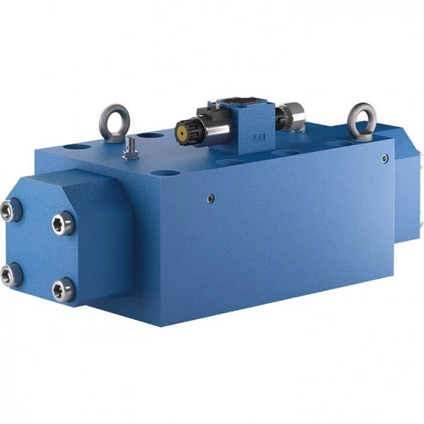
Directional spool valves, pilot operated, with electro-hydraulic actuation LS 1376
Цена по запросу Стоимость зависит от выбранного способа оплаты и количества товара.
Не отвечаем 5 минут — скидка на весь заказ!
Нужна скидка? Звони — сделаем лучшее предложение
Работаем по всей России
Возможны самовывоз и доставка по всей территории России
Надежность
Профессиональная поддержка
Description
- Size 62
- Component series 1X
- Maximum operating pressure 250 bar
- Maximum flow 1500 l/min
Features
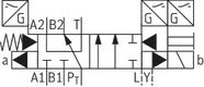
- 6/2 directional design
- For subplate mounting
- Wet-pin DC solenoid
- Electrical connection as individual connection
- Manual override
- Spool position monitoring
Product description
Valve type LS 1376 is a directional spool valve with electro-hydraulic actuation. It controls the start, stop and direction of a flow.
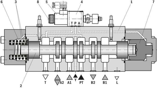
The directional valve basically consists of the main valve with housing (1), the main control spool (2), the compression springs (3), as well as the pilot control valve (4) with solenoid (5). The spring chamber (6) is internally connected to port PT. The pilot control valve (4) is externally supplied with pilot oil via channel Y and supplies the control chamber of the control spool (7).
The main control spool (2) is held in spool position “b” by the pressurization of the two front faces with identical pilot pressure. In this spool position, the control spool (7) rests on the housing and fixes the position of the main control spool (2). Pressure relief of the control spool (7) area brings the main control spool (2) into spool position “a”. Via the pilot control valve (4), the unloaded area of the control spool (7) internally displaces the returning pilot oil into channel T.
Upon actuation of the pilot control valve (4) via the solenoid (5), the control spool (7) and thus the main control spool (2) is displaced to the left.
The manual override (8) at the pilot control valve (4) allows for an active opening of the seat poppet without solenoid energization.
Notes:
With this valve, the compression springs (3) do not have a reset function. In the depressurized condition and with horizontal installation, they hold the main control spool (2) in the basic position.
When determining the minimum pilot pressure, the pressure in the tank line is to be considered.
Type code
| 01 | 02 | 03 | 04 | 05 | 06 | 07 | 08 | 09 | 10 | 11 | |||
| LS 1376 | X201 | - | 1X | / | 10S | C | G110 | N9 | K4 | / | B22 | * |
| 01 | Directional spool valve, pilot-operated, electro-hydraulically actuated, with spool position monitoring | LS 1376 |
| 02 | see symbol | X201 |
| 03 | Component series 10 ... 19 (10 ... 19: unchanged installation and connection dimensions) | 1X |
| Pilot control valve | ||
| 04 | Directional seat valve (data sheet 22045) | 10S |
| 05 | Direct voltage 110 V | G110 |
| For other voltages, frequencies and electric data, see data sheet 22045 | ||
| 07 | With concealed manual override | N9 |
| Other versions available on request | ||
| Electrical connection | ||
| 08 | Without mating connector; connector DIN EN 175301-803 | K4 1) |
| For further electrical connections, see data sheet 22045 | ||
| Throttle insert | ||
| 09 | Throttle Ø 2.2 mm | B22 |
| Seal material | ||
| 10 | NBR seals | no code |
| FKM seals | V | |
| Observe compatibility of seals with hydraulic fluid used. (Other seals upon request) | ||
| 11 | Further details in the plain text | * |
| 1) | Mating connectors, separate order, see data sheet 08006 and 22045. |
Technical data
(For applications outside these values, please consult us!)
general
| Size | 62 | ||
| Weight (approx.) | kg | 167 | |
| Installation position | horizontal | ||
| Ambient temperature range | °C | -30 … +50 | |
| Storage temperature range | °C | -20 … +70 | |
| Surface protection | Valve body | Painting | |
| MTTFD values according to EN ISO 13849 | Years | 150 | |
hydraulic
| Size | 62 | ||
| Maximum operating pressure | bar | 250 | |
| Maximum pilot pressure | bar | 250 | |
| Minimum pilot pressure | bar | 25 | |
| Maximum flow | l/min | 1500 | |
| Hydraulic fluid | see table | ||
| Hydraulic fluid temperature range | at the valve working ports of the valve | °C | -30 … +70 |
| Viscosity range | mm²/s | 2.8 … 380 | |
| Maximum admissible degree of contamination of the hydraulic fluid 1) | Class 20/18/15 according to ISO 4406 (c) | ||
| 1) | The cleanliness classes specified for the components must be adhered to in hydraulic systems. Effective filtration prevents faults and simultaneously increases the life cycle of the components. For the selection of the filters, see www.boschrexroth.com/filter. |
| Hydraulic fluid | Classification | Suitable sealing materials | Standards | Data sheet | |
| Mineral oils | HL, HLP, HLPD, HVLP, HVLPD | NBR, FKM | DIN 51524 | 90220 | |
| Bio-degradable | Insoluble in water | HETG | NBR, FKM | ISO 15380 | 90221 |
| HEES | FKM | ||||
| Soluble in water | HEPG | FKM | ISO 15380 | ||
| Flame-resistant | Water-free | HFDU, HFDR | FKM | ISO 12922 | 90222 |
| Important information on hydraulic fluids:
| |||||
electrical
| Size | 62 | ||
| Switching time according to ISO 6403 1) | ON | s | 1.2 |
| OFF | s | 1.8 | |
| 1) | The switching times were determined at a hydraulic fluid temperature of 40 °C and a viscosity of 46 mm2/s. Deviating hydraulic fluid temperatures can result in different switching times. Switching times change dependent on operating time and application conditions. |
When establishing the electrical connection, the protective grounding conductor (PE) must be connected correctly.
Notice:
For additional technical data refer to data sheet 22045
Diagrams/characteristic curves
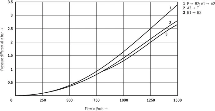
(measured with HLP46, ϑOil = 40 °C ± 5 °C)
Δp-qV characteristic curves
Symbols/Circuit diagrams
Dimensions
Dimensions in mm
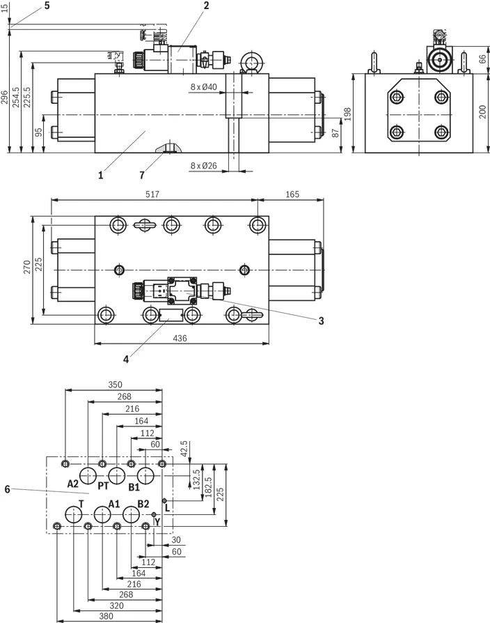
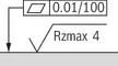 Required surface quality of the valve contact surface |
| 1 | Main valve |
| 2 | Pilot control valve type M-3SED 10 …; dimensions see data sheet 22045 and 24830 |
| 3 | Name plate pilot control valve |
| 4 | Name plate complete valve |
| 5 | Space required to remove the mating connector |
| 6 | Machined valve contact surface |
| 7 | Seal rings |
Valve mounting screws (separate order)
8 hexagon socket head cap screws ISO 4762 - M24 x 120 - 10.9-flZn-240h-L
(friction coefficient μtotal = 0.09 to 0.14);
Tightening torque MA = 760 Nm ±10%,
material no. R913000522
Notice:
The dimensions are nominal dimensions which are subject to tolerances.
Ordering codes
Downloads
 | Directional spool valves, pilot operated, with electro-hydraulic actuation Data Sheet | RE24781 | 2015-05-01 | English | PDF | 592k Product Groups: Pilot operated Type LS 1376 |
Отзывы о товаре
Аналогичные товары
Официальный поставщик Bosch Rexroth
Продажи на территории России
Оптовые и розничные продажи
Снижение логистических расходов
Индивидуальные условия
Выгода без посредников
Единая система поставок
Весь ассортимент на складе