
Артикул: RX7148
В наличии
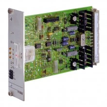
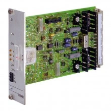
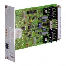
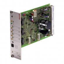
Valve amplifiers for servo-valves VT 11021-1X
Цена по запросу Стоимость зависит от выбранного способа оплаты и количества товара.
Не отвечаем 5 минут — скидка на весь заказ!
Нужна скидка? Звони — сделаем лучшее предложение
Работаем по всей России
Возможны самовывоз и доставка по всей территории России
Надежность
Профессиональная поддержка
Description
- Component series 1X
- Analog, Modular design
- For valves: 4WS2EM 6-2X, 4WS2EM 10-5X and 4WS2EM 16-2X
Features
- Differential input for voltage
- Output stage with dither signal
- Reverse polarity protection for the operating voltage
Product description
The amplifier module is snapped onto top hat rails according to EN 60715. The electrical connection is established via screw terminals. The module is operated with 24 V direct voltage.
The command value ±10 V is connected to the differential input. The output current of the downstream U/I converter controls the servo valve.
At the trimming potentiometers Gw, Zw and GD, the following external settings are possible:
Max. output current with "Gw"
Offset current with "Zw"
Amplitude of the dither signal with "GD"
Type code
| 01 | Valve amplifier for servo valves without electrical position feedback, analog, modular design, for valves 4WS2EM 6-2X and 4WS2EM 10-5x | VT 11021
|
| 02 | Component series 10 ... 19 (10 ... 19: unchanged installation and connection dimensions) | 1X |
| 03 | Further details in the plain text | * |
| 01 | 02 | 03 | ||
| VT 11021 | ‒ | 1X | / | * |
Technical data
General
| Component series | 1X | |
| Type of electronics | Analog | |
| Design | Modul |
Voltage supply
| Operating voltage | Nominal | U | V | 24 |
| Lower limit value | UB(t)min | V | 21 | |
| Upper limit value | UB(t)max | V | 35 | |
| Power consumption | P | VA | 8 | |
| Current consumption | max. | Imax | A | 0.3 |
| Fuse | Thermal overload protection (with restart if the value falls below the temperature threshold) | |||
Analog inputs
| Command value | Voltage | Differential input | U | V | 0 … ±10 |
| Input resistance | R | kΩ | ≥ 20 |
Digital inputs
| Controller change-over 1) | U | V | +24 (with J13); 0 (with J12) |
| Backup relay 1) | U | V | +24 (with J13); 0 (with J12) |
| 1) | RE = 700 Ω (relay) |
Solenoid outputs
| Solenoid current | max. | Imax | mA | 60 |
| Dither signal | f | Hz | 340 ±5 % (I = 0 ... 6 mA, 3 mA pre-set) | |
Adjustment options
| Setting range | Solenoid current | % | ± 10 |
Measuring sockets
| Command value | "w" | Uw | V | 0 ... ±10 |
Other information
| Reference voltage | Potentiometer supply | U | V | ±15 ±2 % (Imax = 150 mA) |
| Anschlussart | 6 screw terminals | |||
| Mounting type | Top hat rail TH 35-7.5 according to EN 60715 | |||
| Protection class according to EN 60529 | IP 20 | |||
| Ambient temperature range | ϑ | °C | 0 … 50 | |
| Storage temperature range | ϑ | °C | -20 … 70 | |
| Weight | m | kg | 0.13 | |
(For applications outside these values, please consult us!)
Operating and display elements
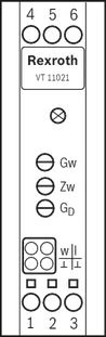
LED displays
| LED | Internal supply voltage |
Potentiometer
| Gw | Amplitude attenuator |
| Zw | Offset |
| GD | Dither amplitude |
Measuring sockets
| w | Command value |
| I | Actual current value (10 mV ≙ 1 mA) |
| ⊥ | Reference potential |
Symbols/Circuit diagrams
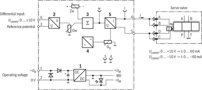
| 1 | Power supply unit |
| 2 | Differential amplifier |
| 3 | Summing device |
| 4 | Dither generator |
| 5 | U/I converter |
| Gw | Amplitude attenuator |
| Zw | Offset |
| GD | Dither amplitude |
Dimensions
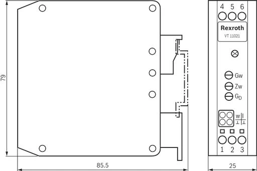
Dimensions in mm
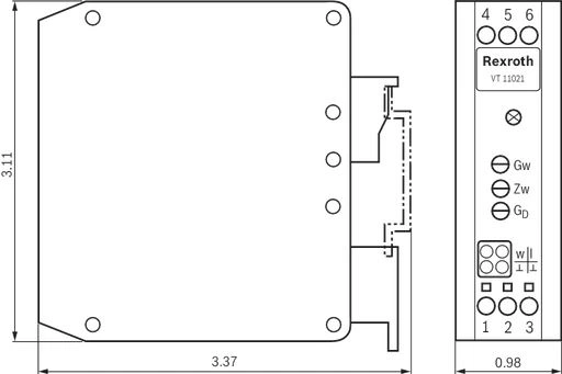
Dimensions in mm
Project planning information
The amplifier module may only be wired when de-energized.
The distance to radios must be sufficient (>> 1m).
Shield command value lines, do not install them close to power cables.
Do not use free-wheeling diodes in the solenoid conductors.
With a strongly fluctuating operating voltage, it may in individual cases be necessary to use an external smoothing capacitor with a capacity of at least 2200 µF.The amplifier module may only be wired when de-energized.
The distance to radios must be sufficient (>> 1m).
Shield command value lines, do not install them close to power cables.
Do not use free-wheeling diodes in the solenoid conductors.
With a strongly fluctuating operating voltage, it may in individual cases be necessary to use an external smoothing capacitor with a capacity of at least 2200 µF.
Recommendation:
Capacitor module VT 11110 (see data sheet 30750); sufficient for up to 3 amplifier modules
Downloads

Отзывы о товаре
Аналогичные товары
Официальный поставщик Bosch Rexroth
Продажи на территории России
Оптовые и розничные продажи
Снижение логистических расходов
Индивидуальные условия
Выгода без посредников
Единая система поставок
Весь ассортимент на складе