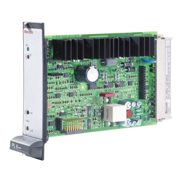
Артикул: RX7120
В наличии
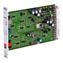
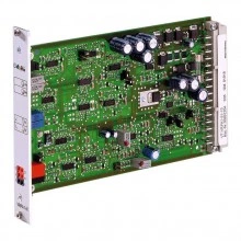
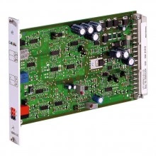
Valve amplifiers for proportional pressure, proportional flow control valves and high-response valves VT-VRPA1-527-1X/V0/...
Цена по запросу Стоимость зависит от выбранного способа оплаты и количества товара.
Не отвечаем 5 минут — скидка на весь заказ!
Нужна скидка? Звони — сделаем лучшее предложение
Работаем по всей России
Возможны самовывоз и доставка по всей территории России
Надежность
Профессиональная поддержка
Description
- Component series 1X
- Analog, Euro-card format
- For valves: DBETFX, DREB6X, 4WRP6EA, 3FREZ
Features
- Controlled output stage
- Closed-loop position control with PID characteristics
- Fast energization and fast deletion for short actuating times
- Enable input
- Short-circuit-proof outputs
- Adjustable zero point and sensitivity
Type code
| 01 | Valve amplifier for high-response valves with one solenoid, analog, euro-card format | VT-VRPA1 |
| 02 | For valves: DBETFX, DREB6X, 4WRP6EA, 3FREZ | 527 |
| 03 | Component series 10 ... 19 (10 ... 19: unchanged installation and connection dimensions) | 1X |
| 04 | Version: standard | V0 |
| 05 | Option: Pressure valves | PV |
| Option: Throttle/flow control valves | QV | |
| 01 | 02 | 03 | 04 | 05 | ||||
| VT-VRPA1 | ‒ | 527 | ‒ | 1X | / | V0 | / |
Technical data
Position transducer
| Cable length | L | 50 m at 100 pF/m |
Supplementary information
| Reference voltage | Potentiometer supply | U | V | 10 (Imax = 50 mA) |
| Special features | Short-circuit-proof outputs, cable break detection for actual value line, position control with PID behavior, fast energization and fast deletion for short actuating times | |||
| Anschlussart | 32-pin male connector, DIN 41612, form F | |||
| Ambient temperature range | ϑ | °C | 0 … 70 | |
| Storage temperature range | ϑ | °C | -20 … 70 | |
| Weight | m | kg | 0.37 | |
Anzeigen
| LED display | Green 1 | Enable | |
| Yellow 1 | Cable break actual value | ||
| Red | UB too low |
Adjustment options
| Zero point calibration | % | ± 10 | ||
| Range sensitivity adjustment | Setting condition | % | 50 ... 100 | |
Solenoid outputs
| Solenoid current | max. | Imax | A | 2.7 |
| Power | P | VA | 25 | |
| Solenoid output | Other properties | clocked | ||
| Cable length | for 1.5 mm2 | m | 20 | |
| for 2.5 mm2 | m | 60 | ||
Analog outputs
| Test point 1) | Actual value | 0 ... 10 |
| 1) | 0 V at solenoid current = 0 ( output stage not enabled), 10 V at solenoid current = maximum |
Analog inputs
| Command value source | Potentiometer 1 kΩ supplied with 10 V internal reference voltage, external signal source | ||||
| Command value | Voltage (differential input) | U | V | 0 ... 10 | |
| Voltage | grounded on one side, first input | Ucommand | V | 0 … 10 | |
| Voltage | grounded on one side, second input | Ucommand | V | 0 … 10 | |
| Actual value valve | Voltage | U | 10.2 (7.8 kHz) | ||
Voltage supply
| Operating voltage | Nominal | U | V | 24 |
| Lower limit value | UB(t)min | V | 21 | |
| Upper limit value | UB(t)max | V | 40 | |
| Ripple 1) | % | < 10 | ||
| Power consumption | max. | Smax | VA | 35 |
| Current consumption | max. | Imax | A | 1.5 |
| 1) | In case of ripple > 10 %, an upstream smoothing capacitor is required (recommendation: capacitor module VT 11110) |
Digital outputs
| Cable break error message | No error 1) | U | V | 24 V |
| Error | U | V | 0 V |
| 1) | Imax = 100 mA |
Digital inputs
| Enable | On (active) | U | V | 8.5 ... 40 |
General
| Component series | 1X | ||
| Material number | Data sheet | 1819929062 | |
| Type of electronics | Analog | ||
| Design | Euro-card | ||
(For applications outside these values, please consult us!)
Operating and display elements
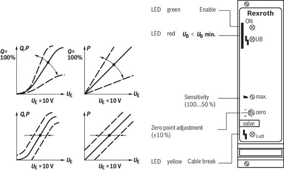
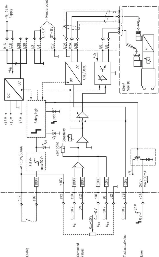
Symbols/Circuit diagrams
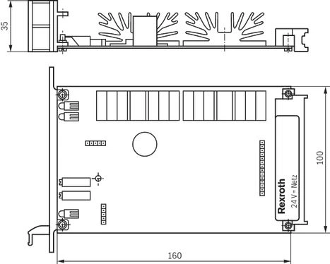
Dimensions
2/2 directional seat valve (“NK”) and 3/2 directional seat valve (“CK”)
Dimensions in mm
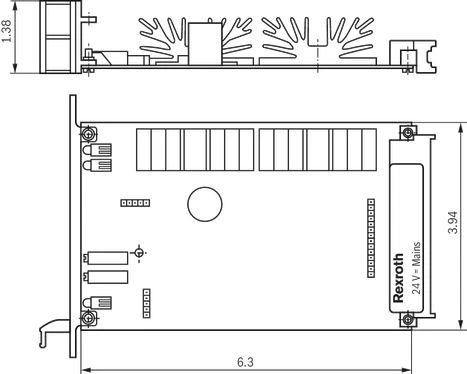
Dimensions in mm
Project planning information
The amplifier card may only be unplugged and plugged when de-energized.
The distance to aerial lines, radios, and radar systems has to be at least 1 m.
Do not lay solenoid and signal lines near power cables.
For signal lines and solenoid conductors, we recommend using shielded cables.
The cable shield must be connected to the control cabinet extensively and as short as possible.
The valve solenoid must not be connected to free-wheeling diodes or other protection circuits.
The cable lengths and cross-sections specified in the technical data must be complied with.
Mounting
Wiring information
Power zero b2 and control zero b12 are to be bridged.
If the power supply unit is < 1 m away, directly to DIN connector.
In case of distances > 1 m, lead the control zero separately to the ground.
Downloads
 | Electric amplifiers Data Sheet | RE30052 | 2012-02-28 | English | PDF | 395k Product Groups: Valve amplifiers VT-VRPA1-5...-1X/V0/... |
| Amplificateurs électriques Data Sheet | RF30052 | 2012-02-28 | French | PDF | 398k Product Groups: Valve amplifiers VT-VRPA1-5...-1X/V0/... |
| Amplificador eléctricos Data Sheet | RS30052 | 2012-02-24 | Spanish | PDF | 396k Product Groups: Valve amplifiers VT-VRPA1-5...-1X/V0/... |
| Elektrische Verstärker Data Sheet | RD30052 | 2012-02-28 | German | PDF | 406k Product Groups: Valve amplifiers VT-VRPA1-5...-1X/V0/... |
| 电气放大器 Data Sheet | RC30052 | 2012-02-29 | Chinese | PDF | 592k Product Groups: Valve amplifiers VT-VRPA1-5...-1X/V0/... |
Отзывы о товаре
Аналогичные товары
Официальный поставщик Bosch Rexroth
Продажи на территории России
Оптовые и розничные продажи
Снижение логистических расходов
Индивидуальные условия
Выгода без посредников
Единая система поставок
Весь ассортимент на складе