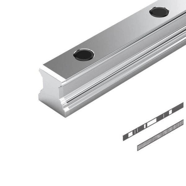
Артикул: RX8114
В наличии
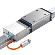
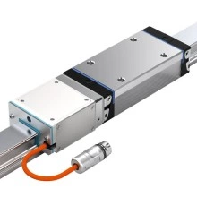
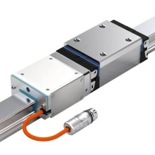
Ball Guide Rails SNS with mounting hole plugs
Цена по запросу Стоимость зависит от выбранного способа оплаты и количества товара.
Не отвечаем 5 минут — скидка на весь заказ!
Нужна скидка? Звони — сделаем лучшее предложение
Работаем по всей России
Возможны самовывоз и доставка по всей территории России
Надежность
Профессиональная поддержка
Description
- For mounting from above with plastic mounting hole plugs
- With integrated scale
Product description
Product description
Technical data
Guide Rail
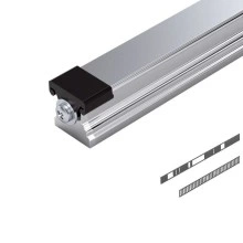
The incremental scale and the reference marks and the absolute code band are integrated in the guide rail for the measuring system. All tuning work has therefore been completed at the plant prior to shipment. The user does not incur any extra installation costs for the measurement system. Moreover, the system does not take up any additional space. Usage together with clamping or braking elements is prohibited.
Scale
The so called scales (1/2) are integrated in the guide rail. They consist of a steel mesh band. For IMS-I, an incremental scale and reference marks are integrated in the guide rail,
for IMS-A, these reference marks are replaced by an absolute code band.
Incremental scale (1):
When scanned, the scale itself delivers only ascending or descending numerical values (incremental signals). The precision of the scale is determined by the accuracy class.
Absolute code band (2):
The absolute code band provides absolute position information when the system is switched on.
Reference marks:
When scanned, the scale itself delivers only ascending or descending numerical values (incremental signals). This incremental measuring method does not allow the absolute position of the measuring system to be detected. An additional reference is needed to determine the absolute position of the Runner Block on the Guide Rail.
This can be provided in different ways:
- Single reference mark
- External mechanical stop or switch
Scale protection
The cover (3) (stainless-steel band) protects the scale (1/2) from contamination. The stainless steel band is connected to the rail by laser welding. This achieves protection type IP67.
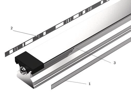
| 1 | Incremental scale high-precision division by 1,000 µm |
| 2 | Absolute code band |
| 3 | Cover |
Mounting the guide rail and covering the fastening screws
The guide rail is mounted from above. The mounting holes can be sealed by a cover strip (4) or mounting hole plugs (5).
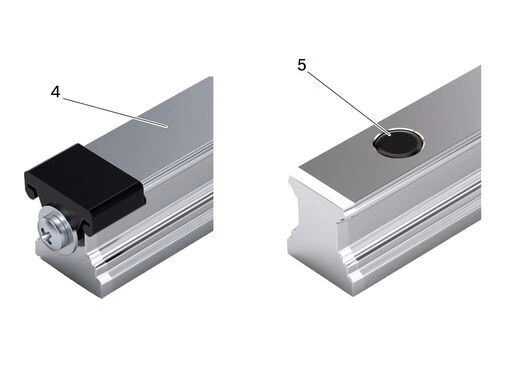
| 4 | Guide rail with cover strip and protective caps |
| 5 | Guide rail with plastic or steel mounting hole plugs |
Single, absolute reference mark of the Guide Rail
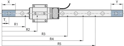
A single, absolute reference mark is a bore that is machined into the Guide Rail on the side opposite the scale. It is closed with a brass pin to protect it from contamination and damage. This sensor must travel past this reference mark to detect the position. Up to 5 single reference marks (R1 ... R5) can be machined into the Guide Rail (please state the required positions when ordering). The minimum distance between two reference marks is 10 mm.
IMS-I
Permitted positions of single reference marks (7 Coding, feature: R1 ... R5)
Due to mechanical boundary conditions, the reference mark positions should be chosen as specified in the drawing below. No reference marks may be positioned in the areas X and Y. In other words, define the positions for R1 … R5 so that these are >X and >Y. Specify the positions in increments of 1 mm.
Example: Size 20: R1 = 155 mm, Rn = rail length - 63 mm, with cover strip and protective end caps (AB).
Between the single reference marks there must be a minimum space of 10 mm
| Size | Dimensions (mm) | |||
| Feature AB (R1605.6...) | Feature AK (R1605.0...) | |||
| X | Y | X | Y | |
| 20 | 154 | 62 | 134 | 42 |
| 25 | 170 | 62 | 150 | 42 |
| 30 | 184 | 62 | 164 | 42 |
| 35 | 203 | 62 | 183 | 42 |
| 45 | 238 | 62 | 218 | 42 |
Dimensions
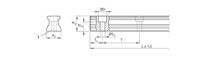
| 1) | For manufacturing reasons, rails may have a flat underside (without groove). |
Dimensions
| Size | 20 | 25 | 30 | 35 | 45 | |
| A2 | mm | 20 | 23 | 28 | 34 | 45 |
| D | mm | 9.4 | 11 | 15 | 20 | |
| H2 | mm | 20.55 | 24.25 | 28.35 | 31.85 | 39.85 |
| Lmin | mm | 220 | 240 | 250 | 270 | 310 |
| Lmax | mm | 4500 | ||||
| N6 | 13.2 mm ±0.5 | 15.2 mm ±0.5 | 17 mm ±0.5 | 20.5 mm ±0.5 | 23.5 mm ±0.5 | |
| S5 | mm | 6 | 7 | 9 | 14 | |
| T | mm | 60 | 80 | 105 | ||
| T1 min | mm | 10 | 12 | 16 | ||
| T1 s | mm | 28 | 38 | 50.5 | ||
| T1 max | mm | 50 | 68 | 89 | ||
Project planning information
Available versions
|
| Ball Guide Rails SNS | ||
| Size | 20 | P | ✓ |
| S | ✓ | ||
| 25 | P | ✓ | |
| S | ✓ | ||
| 30 | P | ✓ | |
| S | ✓ | ||
| 35 | P | ✓ | |
| S | ✓ | ||
| 45 | P | ✓ | |
| S | ✓ | ||
Product Overview and Type Designation, Ball Guide Rails
Mounting
Mounting instructions / maintenance instructions
Safety Instructions
Safety instructions
Downloads
 | Integrated Measuring System IMS for Ball and Roller Rail systems / Instructions for electrical interfaces / only PDF Manual | R320103166_EN | 2017-10-01 | English | PDF | 2.4MB Product Groups: Integrated measuring systems |
| Integrated Measuring System IMS for Ball and Roller Rail Systems Manual | R320103262_EN | 2020-07-01 | English | PDF | 1.8MB Product Groups: Integrated measuring systems |
| Catalog Integrated Measuring System IMS for Ball and Roller Rail Systems Catalog | R999000487 | 2020-06-01 | English | PDF | 2.7MB Product Groups: Ball Rail Systems, Roller Rail Systems, Integrated measuring systems Catalog Integrated Measuring System IMS for Ball and Roller Rail Systems |
Отзывы о товаре
Официальный поставщик Bosch Rexroth
Продажи на территории России
Оптовые и розничные продажи
Снижение логистических расходов
Индивидуальные условия
Выгода без посредников
Единая система поставок
Весь ассортимент на складе