

Артикул: RX7702
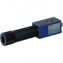
Proportional pressure relief valve, pilot-operated, with integrated electronics (OBE) DBEME
Доступно к заказу
Цена по запросу
И выбери подходящего.
Description
- Component series 7x
- Max. operating pressure 350 bar
Features
- Pilot-operated valves for system pressure limitation
- Controlled by proportional solenoid
- For subplate mounting and threaded connection: porting pattern according to ISO 6264
- Maximum pressure relief function
- Valve and control electronics from a single source
- Integrated electronics (OBE) with little manufacturing tolerance of the command value pressure characteristic curve
Product description
Function, section
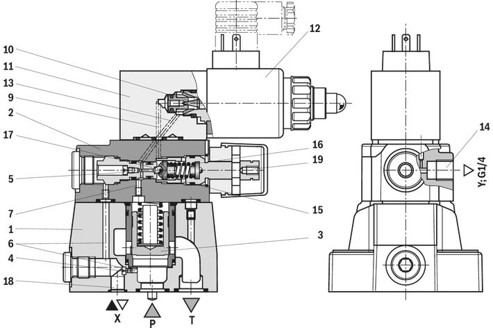
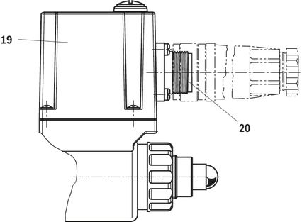
Valves of type DBEME are pilot-operated pressure relief valves with integrated electronics (OBE). They are used to limit the operating pressure in hydraulic systems. These valves can be used for the stepless setting of the pressure to be limited dependent on the electrical command value. The valves basically consist of the housing (1) with main spool insert (3), the sandwich plate valve with maximum pressure limitation (2) and the proportional pilot control valve (11). On the proportional solenoid, there is moreover a housing with the control electronics (19). Supply and command value voltage are applied at the connector (20). At the factory, the command value pressure characteristic curve is adjusted with little manufacturing tolerance.
Type DBEME...
The pressure applied to channel P acts on the main spool (3). Simultaneously, the pressure at port P is applied to the spring-loaded side of the main spool (3) via the control lines (6, 7) provided with nozzles (4, 5). Via the connecting bore (9), the pressure is simultaneously applied to the
poppet (10) of the proportional pilot control valve (11). The hydraulic force at the pilot poppet (10) acts against the command value-dependent force of the proportional solenoid (12). If the hydraulic force exceeds the solenoid force, the pilot poppet is opened (10). The pilot oil can now flow via the control line (13) into port Y (14) and to the tank; thus, a pressure drop results at the main spool (3) over the control lines (6, 7). The connection from port P to T is released. The main spool (3) controls the set operating pressure at port P.
As hydraulic protection against inadmissibly high pressures, a spring-loaded pressure relief valve (2) has been integrated. This maximum pressure limitation is pre-set to the relevant pressure rating (see table page 6). In the operating range of the valve, the poppet (15) is held
on the valve seat (17) by the spring (16) and is thus closed. If the pressure in the spring chamber of the main spool (3) exceeds the maximum admissible set pressure of the valve, the poppet (15) is pressed against the compression spring (16) and the connection into the spring chamber is opened. Via port Y (14), the pilot oil flows into the tank. Due to the control lines (6, 7), a pressure drop occurs at the main spool (3). The connection from port P to T is released. The main spool (3) controls the set maximum operating pressure in port P. Via the adjustment element (19), the pre-set pressure can be reduced, if necessary. Port Y
(14) must be externally piped to the tank. The connection to the tank should be depressurized. Via port X (18), the valve may be unloaded or the maximum pressure may be limited.
Type code
| 01 | 02 | 03 | 04 | 05 | 06 | 07 | 08 | 09 | 10 | 11 | 12 | 13 | 14 | 15 | ||
| DBE | M | E | ‒ | 7X | / | G24 | K31 | * |
| 01 | Proportional pressure relief valve for external control electronics | DBE |
| 02 | Maximum pressure relief function | M 1) |
| 03 | With integrated electronics (OBE) | E |
| Size | ||
| 04 | Size 10 | 10 |
| Size 25 | 20 | |
| Size 32 | 30 | |
| 05 | Component series | no code |
| Threaded connection | G | |
| 06 | Component series 70 ... 79 (70 ... 79: unchanged installation and connection dimensions) | 7X |
| Pressure rating 2) | ||
| 07 | Up to 50 bar | 50 |
| Up to 100 bar | 100 | |
| Up to 200 bar | 200 | |
| Up to 315 bar | 315 | |
| Up to 350 bar | 350 | |
| 08 | Pilot oil return, external | Y |
| Bleed port X, external pilot oil return | XY | |
| 09 | Direct voltage 24 V | G24 |
| 10 | 1600 mA coil | no code |
| 800 mA coil (only possible for DBET-6X (external control electronics) | -8 3) | |
| Electrical connection | ||
| 11 | Without mating connector, connector according to DIN EN 175201-804 | K31 4) |
| Electrical interface | ||
| 12 | Command value 0 … 10 V | A1 |
| Command value 4 to 20 mA | F1 | |
| Seal material | ||
| 13 | NBR seals | M |
| FKM seals | V | |
| Observe compatibility of seals with hydraulic fluid used. (Other seals upon request) | ||
| 14 | Pipe thread according to ISO 228/1 | no code 5) |
| UNF thread according to ASME B1.1 | /12 5) | |
| 15 | Further details in the plain text | * |
| 1) | The maximum pressure limitation only serves as protection against overpressure in case of an error in the pilot valve (e. g. in case of contamination or over-current). | |
| 2) | Special version DBEME-SO699 in size 10 and 20 available up to a pressure rating of 500 bar. | |
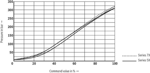
| 3) | Replacement for series 3X and series 5X SO1 (comparison see characteristic curve). All specified characteristics (hydraulic and electric) refer to the version with 1600 mA coil. | |
| 4) | Mating connectors (separate order) | |
| 5) | Only possible with version G | |
Technical data
general
| Type | DBEME | DBEMEG | DBEME | DBEMEG | DBEME | DBEMEG | |
| Size | 10 | 25 | 32 | ||||
| Component series | 7x | ||||||
| Installation position | Any | ||||||
| Earth | kg | 4.7 | 7.2 | 5.5 | 6.94 | 6.6 | |
| Storage temperature range | °C | -20 … +80 | |||||
| Ambient temperature range | °C | -20 … +50 | |||||
hydraulic
| Size | 10 | 25 | 32 | ||
| Maximum operating pressure | bar | 350 | |||
| Port P | bar | 350 | |||
| Port X | bar | 350 | |||
| Port T | bar | 315 | |||
| Maximum set pressure | Pressure rating 50 bar | bar | 50 | ||
| Pressure rating 100 bar | bar | 100 | |||
| Pressure rating 200 bar | bar | 200 | |||
| Pressure rating 315 bar | bar | 315 | |||
| Pressure rating 400 bar | bar | 350 | |||
| Minimum set pressure | See characteristic curve | ||||
| Maximum pressure relief function | Pressure rating 50 bar 1) | bar | 75 | ||
| Pressure rating 100 bar | bar | 135 | |||
| Pressure rating 200 bar | bar | 240 | |||
| Pressure rating 315 bar | bar | 350 | |||
| Pressure rating 350 bar | bar | 390 | |||
| Pilot oil volume range | cm³ | 0,4 … 1 | 0,4 … 1,5 | ||
| Maximum flow | l/min | 275 | 550 | 700 | |
| Hydraulic fluid | see table | ||||
| Hydraulic fluid temperature range | °C | -20 … +80 | |||
| Viscosity range | mm²/s | 15 … 380 | |||
| Maximum admissible degree of contamination of the hydraulic fluid, cleanliness class according to ISO 4406 (c) 2) | Class 20/18/15 according to ISO 4406 (c) | ||||
| Hysteresis 3) | % | ≤ 5 | |||
| Linearity 3) | % | ± 3.5 | |||
| Manufacturing tolerance of the command value pressure characteristic curve, related to the hysteresis characteristic curve, pressure increasing 4) | % | ± 1.5 | |||
| Step response 5) | 10% → 90% | ms | ≈ 100 | ||
| 90% → 10% | ms | ≈ 100 | |||
| 1) | set at the factory |
| 2) | The cleanliness classes specified for the components must be adhered to in hydraulic systems. Effective filtration prevents faults and simultaneously increases the life cycle of the components. For the selection of the filters, see www.boschrexroth.com/filter. |
| 3) | Of the maximum set pressure |
| 4) | of the maximum set pressure, related to the hysteresis characteristic curve, pressure increasing |
| 5) | measured with standing hydraulic fluid column, 0.2 liters at port A |
| Hydraulic fluid | Classification | Suitable sealing materials | Standards |
| Mineral oils and related hydrocarbons | HL, HLP | NBR / FKM | DIN 51524 |
| Bio-degradable - insoluble in water | HETG | NBR / FKM | VDMA 24568 |
| HEES | FKM | ||
| Bio-degradable - soluble in water | HEPG | FKM | VDMA 24568 |
| Flame-resistant - water-free | HFDU, HFDR | FKM | ISO 12922 |
| Flame-resistant - containing water |
HFC | NBR | ISO 12922 |
| Important information on hydraulic fluids: For more information and data on the use of other hydraulic fluids please contact us. The flash point of the process and operating medium used must be 40 K over the maximum solenoid surface temperature. There may be limitations regarding the technical valve data (temperature, pressure range, life cycle, maintenance intervals, etc.). | Flame-resistant - containing water Maximum operating pressure of 210 bar Maximum hydraulic fluid temperature 60 °C Expected life cycle as compared to HLP hydraulic oil 30% to 100% | ||
| Bio-degradable: When using hydraulic fluids that are simultaneously zinc-solving, zinc may accumulate (700 mg zinc per pole tube). | |||
electrical
| Type | DBEME | DBEMEG | DBEME | DBEMEG | DBEME | DBEMEG | |||
| Minimum solenoid current | with 1600 mA - coil | mA | ≤ 100 | ||||||
| with 800 mA - coil | mA | ≤ 100 | |||||||
| Maximum solenoid current | with 1600 mA - coil | mA | 1760 | ||||||
| with 800 mA - coil | mA | 840 | |||||||
| Solenoid coil resistance | Cold value at 20 °C | with 1600 mA - coil | Ω | 5.5 | |||||
| with 800 mA - coil | Ω | 20.6 | |||||||
| Maximum hot value | with 1600 mA - coil | Ω | 8.05 | ||||||
| with 800 mA - coil | Ω | 33 | |||||||
| Duty cycle | % | 100 | |||||||
| Power supply | VDC | 24 | |||||||
| Supply voltage range | VDC | 21 … 35 | |||||||
| Required fuse protection | 2, time-lag | ||||||||
| Command value input | Voltage | V | 0 … 10 | ||||||
| Current | mA | 4 … 20 | |||||||
| Actual value output | Voltage | V | 0 … 1,6 | ||||||
| Current | mA | 0 … 1,6 | |||||||
| Protection class according to DIN EN 60529 | IP65 (If a suitable and a correctly mounted mating connector are used.) | ||||||||
Diagrams/characteristic curves
(measured with HLP46, ϑOil = 40 ±5 °C)
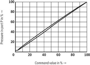
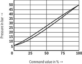
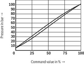
Pressure in port P dependent on the command value
Set pressure dependent on the flow
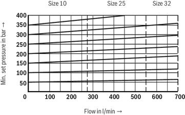
Set pressure dependent on the flow
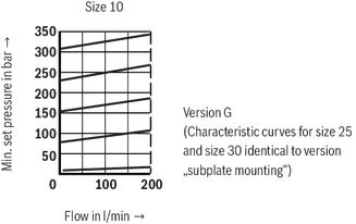
Minimum set pressure with command value 0
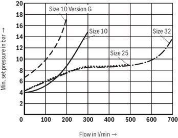
| 1) | The characteristic curves apply for output pressure in T or Y = 0 bar in the entire flow range. Notice: To ensure the minimum set pressure is achieved, the pilot current must not exceed 100 mA. |
Command value pressure characteristic curve; pressure rating 50 bar
Command value pressure characteristic curve; pressure rating 100 bar
Command value pressure characteristic curve; pressure rating 200 bar
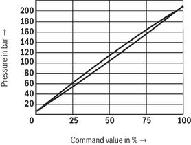
Command value pressure characteristic curve; pressure rating 315 bar
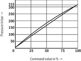
Command value pressure characteristic curve; pressure rating 350 bar
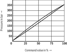
Command value pressure characteristic curve; pressure rating 100 bar; with amplifier VT-VSPA1-1
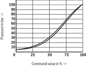
Pressure dependent on the command value / Comparison to series 5X-6X / Pressure rating 315 bar (with amplifier VT-SSPA1-1-1X with 800 mA coil)
Symbols/Circuit diagrams
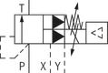
Type DBEME...-7X/...XY...
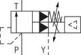
Type DBEME...-7X/...Y...
Electrical connection
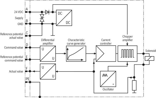
| Pin assignment | Contact | Assignment interface "A1" | Assignment interface "F1" |
| Power supply | A | 24 VDC (u(t) = 21 ... 35 V); Imax ≤ 1,5 A | |
| B | 0 V | ||
| Reference potential actual value | C | Reference contact F; 0 V | Reference contact F; 0 V |
| Differential amplifier input (command value) | D | 0 to 1.6 V actual value (1 mV ≙ 1 mA); | 4 ... 20 mA; Re = 100 kΩ |
| E | Reference potential command value | ||
| Measuring output (actual value) | F | 0 to 1.6 V actual value (1 mV ≙ 1 mA); | |
| PE | connected to solenoid and valve housing | ||
Connection cable
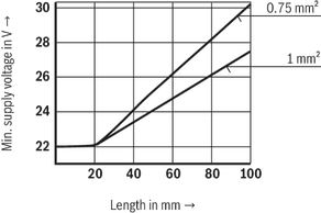
| 1) | Connection cable:- Recommendation 6-wire, 0.75 or 1mm2 plus protective earthing conductor and screening- Connect screening to PE on supply side only- Maximum admissible length 100 m The minimum supply voltage at the power supply unit depends on the length of the supply line (see diagram) |
Integrated electronics (OBE)
Function
The electronics are supplied with voltage via ports A and B. The command value is applied to the differential amplifier ports D and E.Via the characteristic curve generator, the command value solenoid current characteristic curve is adjusted to the valve so that non-linearities in the hydraulic system are compensated and thus, a linear command value pressure characteristic curve is created.The current controller controls the solenoid current independently of the solenoid coil resistance.The power stage of the electronics for controlling the proportional solenoid is a chopper amplifier with a clock frequency of approx. 180 Hz to 400 Hz. The output signal is pulse-width modulated (PWM).For checking the solenoid current, a voltage can be measured at the connector between pin F(+) and pin C(–) that is proportional to the solenoid current. 1 mV corresponds to 1 mA solenoid current.
Block diagram / pin assignment
Dimensions
DBEM(E) 10
Dimensions in mm
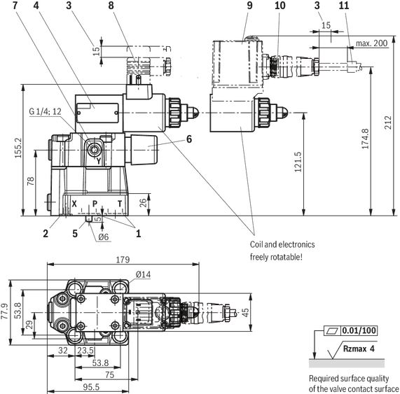
| 1 | Seal rings for ports P and T |
| 2 | Seal ring for port X |
| 3 | Space required to remove the mating connector |
| 4 | Name plate |
| 5 | Locating pin |
| 6 | Maximum pressure relief function |
| 7 | External pilot oil return, separate and depressurized to the tank |
| 8 | Mating connector for type DBEM |
| 9 | Integrated electronics (OBE) |
| 10 | Mating connector for type DBEME |
| 11 | Cable fastening |
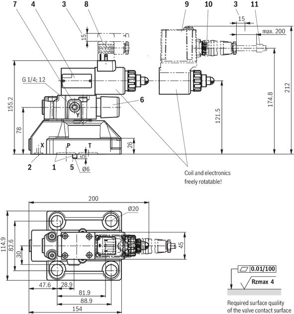
DBEM(E) 10G
Dimensions in mm
| 1 | Space required to remove the mating connector |
| 2 | Name plate |
| 3 | Maximum pressure relief function |
| 4 | External pilot oil return, separate and depressurized to the tank |
| 5 | Mating connector for type DBEM |
| 6 | Integrated electronics (OBE) |
| 7 | Mating connector for type DBEME |
| 8 | Cable fastening |
Recommended valve mounting screws (separate order):
- 4 hexagon socket head cap screws ISO 4762 - M12 x 50 - 10.9-flZn-240h-L
Tightening torque MA = 75 Nm ± 10%; material no. R913000283
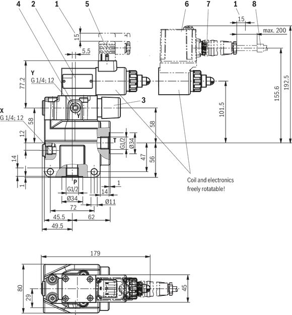
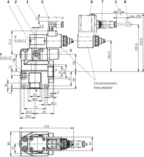
DBEM(E) 20
Dimensions in mm
| 1 | Seal rings for ports P and T |
| 2 | Seal ring for port X |
| 3 | Space required to remove the mating connector |
| 4 | Name plate |
| 5 | Locating pin |
| 6 | Maximum pressure relief function |
| 7 | External pilot oil return, separate and depressurized to the tank |
| 8 | Mating connector for type DBEM |
| 9 | Integrated electronics (OBE) |
| 10 | Mating connector for type DBEME |
| 11 | Cable fastening |
DBEM(E) 20G
Dimensions in mm
| 1 | Space required to remove the mating connector |
| 2 | Name plate |
| 3 | Maximum pressure relief function |
| 4 | External pilot oil return, separate and depressurized to the tank |
| 5 | Mating connector for type DBEM |
| 6 | Integrated electronics (OBE) |
| 7 | Mating connector for type DBEME |
| 8 | Cable fastening |
Recommended valve mounting screws (separate order):
- 4 hexagon socket head cap screws ISO 4762 - M16 x 50 - 10.9-flZn-240h-L
Tightening torque MA = 185 Nm ± 10%; material no. R913000378
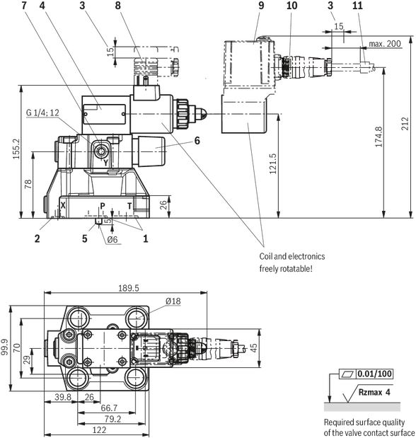
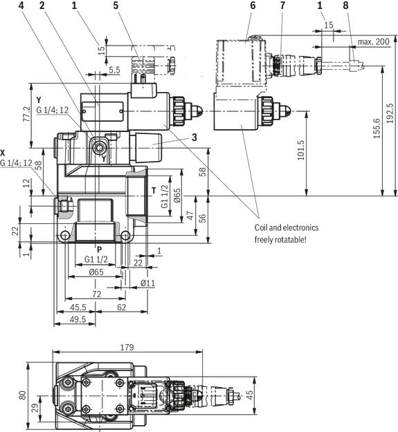
DBEM(E) 30
Dimensions in mm
| 1 | Seal rings for ports P and T |
| 2 | Seal ring for port X |
| 3 | Space required to remove the mating connector |
| 4 | Name plate |
| 5 | Locating pin |
| 6 | Maximum pressure relief function |
| 7 | External pilot oil return, separate and depressurized to the tank |
| 8 | Mating connector for type DBEM |
| 9 | Integrated electronics (OBE) |
| 10 | Mating connector for type DBEME |
| 11 | Cable fastening |
DBEM(E) 30G
Dimensions in mm
| 1 | Space required to remove the mating connector |
| 2 | Name plate |
| 3 | Maximum pressure relief function |
| 4 | External pilot oil return, separate and depressurized to the tank |
| 5 | Mating connector for type DBEM |
| 6 | Integrated electronics (OBE) |
| 7 | Mating connector for type DBEME |
| 8 | Cable fastening |
Recommended valve mounting screws (separate order):
- 4 hexagon socket head cap screws ISO 4762 - M18 x 50 - 10.9-flZn-240h-L
Tightening torque MA = 248 Nm ± 10%; material no. R913031952
Accessories
Mating connectors for valves with round connector, 6-pole + PE
7P Z31
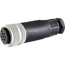
Mating connectors for valves with round connector, 6-pole + PE
7P Z31
- For valves with round connector according to EN 175201-804, 6-pole + PE as well as 6-pole, compatible with VG 95328
Ordering codes
Currently eShop is not available. Please try again later.Downloads
 | Proportional pressure relief valve, pilot operated, Type DBEM and DBEME Data Sheet | RE29361 | 2013-07-31 | English | PDF | 1.2MB Product Groups: Pilot operated |






Цена по запросу
Цена по запросу


Нет отзывов об этом товаре.