
Доступно к заказу
Цена по запросу
И выбери подходящего.
Description
- Size 40 … 300
- Component series 3X
- Maximum operating pressure 25 bar
- Maximum flow 50000 l/min
Features
- For flange connection
- As cartridge valve
- Flange connection according to DIN EN 1092-2 type 21
- 2 pressure ratings
- Adjustment type for pressure adjustment: Sleeve with hexagon and protective cap
Product description
Pressure valves of type L–DB are pilot-operated pressure relief valves for a low preload pressure. They are suitable for high flows.
The valves basically consist of pipeline installation housing (1), main spool guide (2) for accepting the pilot control valve (5) and main spool (3).
Type L–DB
The pressure applied to channel P acts on the main spool (3) and is simultaneously applied to the pilot control valve (5) via nozzles (4) and (6). If the pressure in channel P exceeds the value set at the pilot control valve (5), the latter opens and the pilot oil is directly discharged into channel Y (7).
The main spool (3) moves upwards against the springs (8) and (9) and connects channel P to channel T as long as the pressure exceeds the value set at the pilot control valve.
With version “U”, the main spool (3) is only kept closed by the external spring (9). If the control channel is unloaded, a lower circulation pressure can be achieved.
Type L–DBF
In principle, the function of version “L–DBF” corresponds to the function of type L–DB. The valve is, however, designed as cartridge valve without pipeline housing (1).

Type code
| 01 | 02 | 03 | 04 | 05 | 06 | 07 | 08 | 09 | 10 | 11 | ||
| L–DB | 2 | – | 3X | / | * |
| 01 | Pressure relief valve | L–DB |
| 02 | Pipeline installation | no code |
| Cartridge valve (only size 50 … 200) | F | |
| 03 | Size 40 | 40 |
| Size 50 | 50 | |
| Size 65 | 65 | |
| Size 80 | 80 | |
| Size 100 | 100 | |
| Size 125 | 125 | |
| Size 150 | 150 | |
| Size 200 | 200 | |
| Size 250 | 250 | |
| Size 300 | 300 | |
| 04 | Flange connection according to DIN EN 1092-2 type 21 |
F |
| Cartridge valve | no code | |
| Adjustment type | ||
| 05 | Sleeve with hexagon and protective cap | 2 |
| 06 | Component series 30 ... 39 (30 ... 39: unchanged installation and connection dimensions) | 3X |
| Set pressure | ||
| 07 | Up to 16 bar | 16 |
| Up to 25 bar (only size 80, 100 and 150) | 25 | |
| Pilot oil flow | ||
| 08 | Internal pilot oil supply, external pilot oil return | Y |
| External pilot oil supply, external pilot oil return | XY | |
| 09 | Standard version | no code |
| Valve for minimum cracking pressure | U | |
| Seal material | ||
| 10 | NBR seals | no code |
| FKM seals | V | |
| Observe compatibility of seals with hydraulic fluid used. (Other seals upon request) | ||
| 11 | Further details in the plain text | * |
Technical data
general
| Size | 40 | 50 | 65 | 80 | 100 | 125 | 150 | 200 | 250 | 300 | ||
| Weight | kg | 11 | 15 | 26 | 32 | 50 | 75 | 100 | 180 | 300 | 475 | |
| Installation position | any | |||||||||||
| Ambient temperature range | NBR seals | °C | -30 … +80 | |||||||||
| FKM seals | °C | -15 … +80 | ||||||||||
hydraulic
| Size | 40 | 50 | 65 | 80 | 100 | 125 | 150 | 200 | 250 | 300 | ||
| Maximum operating pressure | Port P | bar | 16 | 16 25 | 16 | 16 25 | 16 | |||||
| Port X | bar | 16 | 16 25 | 16 | 16 25 | 16 | ||||||
| Port T | bar | 16 | 16 25 | 16 | 16 25 | 16 | ||||||
| Maximum counter pressure | Port Y | bar | 16 | 16 25 | 16 | 16 25 | 16 | |||||
| Maximum flow | l/min | 1000 | 1500 | 2700 | 3600 | 6000 | 7000 | 13000 | 24000 | 35000 | 50000 | |
| Hydraulic fluid | see table | |||||||||||
| Hydraulic fluid temperature range | NBR seals | °C | -30 … +80 | |||||||||
| FKM seals | °C | -15 … +80 | ||||||||||
| Viscosity range | mm²/s | 10 … 800 | ||||||||||
| Maximum admissible degree of contamination of the hydraulic fluid 1) | Class 20/18/15 according to ISO 4406 (c) | |||||||||||
| 1) | The cleanliness classes specified for the components must be adhered to in hydraulic systems. Effective filtration prevents faults and simultaneously increases the life cycle of the components. For the selection of the filters, see www.boschrexroth.com/filter. |
| Hydraulic fluid | Classification | Suitable sealing materials | Standards | Data sheet | |
| Mineral oils | HL,HLP | NBR, FKM | DIN 51524 | 90220 | |
| Bio-degradable 2) | Insoluble in water | HETG | FKM | ISO 15380 | 90221 |
| HEES | FKM | ||||
| Soluble in water | HEPG | FKM | ISO 15380 | ||
| Containing water 2) | Water-free | HFDU | FKM | ISO 12922 | 90222 |
| Containing water | HFC (Fuchs Hydrotherm 46M, Petrofer Ultra Safe 620) | NBR | ISO 12922 | 90223 | |
| Important information on hydraulic fluids:
Flame-resistant – containing water:
| |||||
(For applications outside these values, please consult us!)
Notice:
The maximum operating pressure is the sum of the set pressure and counter pressure!
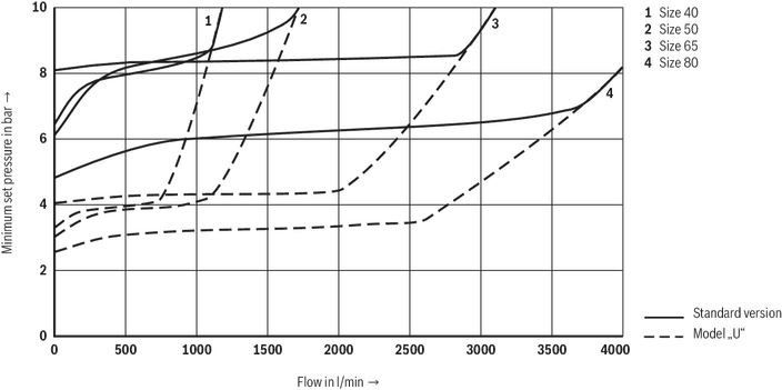
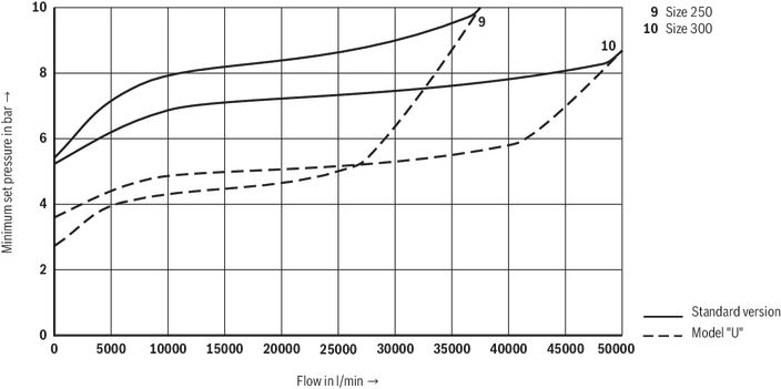
Diagrams/characteristic curves
(simulated with HLP46, ϑOil = 40 °C ±5 °C)
Minimum set pressure dependent on the flow
Size 40 … 80
Minimum set pressure dependent on the flow
Size 100 … 200
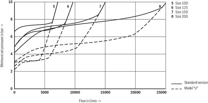
Notice:
The characteristic curves were simulated with external, depressurized pilot oil return.
Minimum set pressure dependent on the flow
Size 250 and 300
Symbols/Circuit diagrams
Type L–DB…Y…

Type L–DB…XY…

Dimensions
Pipeline installation “L–DB”
Dimensions in mm

| 1 | Name plate (position may vary depending on the size) |
| 2 | Ports X for external pilot oil supply |
| 3 | Ports Y for external pilot oil return |
| 4 | Adjustment type "2" |
| 5 | Valve mounting bores |
| 6 | Ring bolt (2 pieces from NG50) |
| NG | L1 | L2 | L3 | L4 | L5 | L6 | H1 | H2 | H3 | H4 | B1 | B2 | ØD1 | ØD3 | ØD4 | ØD5 | ØD6 | |
| mm | mm | mm | mm | mm | mm | mm | mm | mm | mm | mm | mm | mm | mm | mm | mm | mm | ||
| 40 | 198 | ± 2 | 99 | 68 | 42.5 | 77.5 | 117 | 139 | 127 | 97.5 | - | 13 | 95 | 40 | 110 | 150 | 19 | 96 |
| 50 | 228 | ± 2 | 114 | 68 | 42.5 | 75 | 125 | 147 | 135 | 105.5 | 36 | 15 | 100 | 50 | 125 | 165 | 19 | 110 |
| 65 | 288 | ± 3 | 144 | 65 | 52 | 92 | 155 | 183 | 167 | 130 | 36 | 15 | 125 | 65 | 145 | 185 | 19 | 134 |
| 80...16 | 308 | ± 3 | 154 | 65 | 52 | 100 | 170 | 195.5 | 179.5 | 142.5 | 36 | 17 | 140 | 80 | 160 | 200 | 19 | 152 |
| 80...25 | 308 | ± 3 | 154 | 65 | 52 | 100 | 170 | 195.5 | 179.5 | 142.5 | 36 | 14 | 140 | 80 | 160 | 200 | 19 | 152 |
| 100...16 | 348 | ± 3 | 174 | 65 | 52 | 111 | 191 | 220 | 200 | 163 | 36 | 19 | 160 | 100 | 180 | 220 | 19 | 182 |
| 100...25 | 348 | ± 3 | 174 | 65 | 52 | 111 | 191 | 220 | 200 | 163 | 36 | 14 | 160 | 100 | 190 | 235 | 23 | 182 |
| 125 | 398 | ± 3 | 199 | 67 | 50.5 | 122.5 | 245 | 247.5 | 227.5 | 190.5 | 53 | 21 | - | 125 | 210 | 250 | 19 | 215 |
| 150...16 | 478 | ± 3 | 239 | 65 | 53 | 138 | 276 | 265 | 245 | 208 | 53 | 21 | - | 150 | 240 | 285 | 23 | 245 |
| 150...25 | 478 | ± 3 | 239 | 65 | 53 | 138 | 276 | 265 | 245 | 208 | 53 | 14 | - | 150 | 250 | 300 | 28 | 245 |
| 200 | 598 | ± 4 | 299 | 65 | 59 | 170 | 340 | 314 | 294 | 257 | 53 | 25 | - | 200 | 295 | 340 | 23 | 305 |
| 250 | 728 | ± 4 | 364 | 57 | 67 | 205 | 410 | 357 | 333 | 296 | 62 | 27 | - | 250 | 355 | 405 | 28 | 370 |
| 300 | 848 | ± 5 | 424 | 50 | 73.5 | 237.5 | 475 | 398 | 374 | 337 | 62 | 26 | - | 300 | 410 | 460 | 28 | 435 |
Notice:
The tightening torques stated are guidelines when using screws with the specified friction coefficients and when using a manual torque wrench (tolerance ± 10 %).
Notice:
The dimensions are nominal dimensions which are subject to tolerances.
Cartridge valve “L–DBF”
Dimensions in mm

| 1 | Name plate (position may vary depending on the size) |
| 2 | Ports X for external pilot oil supply |
| 3 | Ports Y for external pilot oil return |
| 4 | Adjustment type "2" |
| 6 | Ring bolt (2 pieces from NG50) |
| NG | L3 | L4 | L5 | L6 | H4 | H5 | H6 | B2 |
| mm | mm | mm | mm | mm | mm | mm | mm | |
| 50 | 68 | 42.5 | 75 | 125 | 36 | 60.5 | 24.5 | 100 |
| 65 | 65 | 52 | 92 | 155 | 36 | 75.5 | 32 | 125 |
| 80 | 65 | 52 | 100 | 170 | 36 | 76 | 32 | 140 |
| 100 | 65 | 52 | 111 | 191 | 36 | 76 | 32 | 160 |
| 125 | 67 | 50.5 | 122.5 | 245 | 53 | 82 | 38 | - |
| 150 | 65 | 53 | 138 | 276 | 53 | 79 | 35 | - |
| 200 | 65 | 59 | 170 | 340 | 53 | 82 | 37 | - |
| NG | L1 | L2 | L3 | L4 | L5 | L6 | L7 | ØD1 | ØD3 | ØD4 | ØD5 | ØD6 | ØD7 | G | α | β | n |
| mm | mm | mm | mm | mm | mm | mm | mm | mm | mm | mm | mm | ° | ° | ||||
| 50 | 67.5 | 65.5 | 50 | 40.5 | 35 | 15 | 23 | 110 | 57 | 73 | 89 | 86 | 50 | M12 | 45 | 90 | 4 |
| 65 | 83.5 | 81.5 | 60 | 55.5 | 45 | 20 | 29 | 134 | 75 | 89 | 105 | 105 | 65 | M12 | 45 | 90 | 4 |
| 80 | 94.5 | 92.5 | 65 | 65.5 | 55 | 20 | 29 | 152 | 95 | 104 | 120 | 130 | 80 | M16 | 45 | 90 | 4 |
| 100 | 114.5 | 112.5 | 76 | 75.5 | 67 | 30 | 38 | 182 | 109 | 128 | 148 | 160 | 100 | M20 | 45 | 90 | 4 |
| 125 | 135 | 133 | 100 | 100.5 | 90 | 27 | 34 | 215 | 135 | 156 | 176 | 200 | 125 | M20 | 30 | 60 | 6 |
| 150 | 153.5 | 151.5 | 110 | 110.5 | 105 | 27 | 34 | 245 | 160 | 183 | 203 | 230 | 150 | M20 | 22.5 | 45 | 8 |
| 200 | 197 | 193 | 130 | 155.5 | 155 | 27 | 34 | 305 | 220 | 235 | 265 | 320 | 200 | M20 | 15 | 30 | 12 |
| Standards: | |
| Workpiece edges | DIN ISO 13715 |
| Form and position tolerance | DIN EN ISO 1101 |
| General tolerances for metal-cutting procedures | DIN ISO 2768–mK |
| Tolerance | DIN ISO 8015 |
| Surface condition | DIN EN ISO 1302 |
| Type L–DB (not included in the scope of delivery) | ||||||
| NG | Quantity | Hexagon screw 1) | Hexagon nut | MA in Nm 2) | ||
| 40 | 4 | Hexagon screw ISO 4018 - M16 - 4.6 | Hexagon nut ISO 4032-M16 | 63 | ||
| 50 | 4 | Hexagon screw ISO 4018 - M16 - 4.6 | Hexagon nut ISO 4032-M16 | 63 | ||
| 65 | 4 | Hexagon screw ISO 4018 - M16 - 4.6 | Hexagon nut ISO 4032-M16 | 63 | ||
| 80 | 8 | Hexagon screw ISO 4018 - M16 - 4.6 | Hexagon nut ISO 4032-M16 | 63 | ||
| 100 3) | 8 | Hexagon screw ISO 4018 - M16 - 4.6 | Hexagon nut ISO 4032-M16 | 63 | ||
| 100 4) | 8 | Hexagon screw ISO 4018 - M20 - 4.6 | Hexagon nut ISO 4032-M20 | 123 | ||
| 125 | 8 | Hexagon screw ISO 4018 - M16 - 4.6 | Hexagon nut ISO 4032-M16 | 63 | ||
| 150 3) | 8 | Hexagon screw ISO 4018 - M20 - 4.6 | Hexagon nut ISO 4032-M20 | 123 | ||
| 150 4) | 8 | Hexagon screw ISO 4018 - M24 - 4.6 | Hexagon nut ISO 4032-M24 | 213 | ||
| 200 | 12 | Hexagon screw ISO 4018 - M20 - 4.6 | Hexagon nut ISO 4032-M20 | 123 | ||
| 250 | 12 | Hexagon screw ISO 4018 - M24 - 4.6 | Hexagon nut ISO 4032-M24 | 213 | ||
| 300 | 12 | Hexagon screw ISO 4018 - M24 - 4.6 | Hexagon nut ISO 4032-M24 | 213 | ||
| Type L–DBF (included in the scope of delivery) | ||||||
| NG | Fastening | Assembly aid (from NG80) 5) | ||||
| Quantity | Hexagon socket head cap screw | Material number | MA in Nm | Hexagon socket head cap screw | Material number | |
| 40 | 4 | ISO 4762 - M12 x 70 - 10.9-flZn-240h-L | R913000515 | 35 | ||
| 50 | 4 | ISO 4762 - M12 x 70 - 10.9-flZn-240h-L | R913000515 | 35 | ||
| 65 | 4 | ISO 4762 - M16 x 90 - 10.9-flZn-240h-L | R913000544 | 85 | ||
| 80 | 4 | ISO 4762 - M16 x 90 - 10.9-flZn-240h-L | R913000544 | 85 | ISO 4762 - M16 x 120 - 8.8 | R916445155 |
| 100 | 4 | ISO 4762 - M20 x 100 - 10.9-flZn-240h-L | R913000386 | 165 | ISO 4762 - M20 x 140 - 8.8 | R916445188 |
| 125 | 6 | ISO 4762 - M20 x 100 - 10.9-flZn-240h-L | R913000386 | 165 | ISO 4762 - M20 x 160 - 8.8 | R916445189 |
| 150 | 8 | ISO 4762 - M20 x 100 - 10.9-flZn-240h-L | R913000386 | 165 | ISO 4762 - M20 x 160 - 8.8 | R916445189 |
| 200 | 12 | ISO 4762 - M20 x 100 - 10.9-flZn-240h-L | R913000386 | 165 | ISO 4762 - M20 x 140 - 8.8 | R916445188 |
| 250 | 12 | ISO 4762 - M24 x 100 - 10.9-flZn-240h-L | R913000407 | 285 | ISO 4762 - M24 x 190 - 8.8 | R916309987 |
| 300 | 14 | ISO 4762 - M24 x 100 - 10.9-flZn-240h-L | R913000407 | 285 | ISO 4762 - M24 x 220 - 8.8 | R916445211 |
| 1) In the selection and design, DIN EN 1092-2 is to be observed | |
| 2) Tightening torques have been calculated with hexagon socket head cap screws ISO 4762 (galvanized) | |
| friction coefficient μtotal = 0.09 to 0.14 | |
| 3) Version “16” | |
| 4) Version “25” | |
| 5) In each case 2x |
Notice:
The tightening torques stated are guidelines when using screws with the specified friction coefficients and when using a manual torque wrench (tolerance ± 10 %).
Notice:
The dimensions are nominal dimensions which are subject to tolerances.
Installation bore
Dimensions in mm
Dimensions in mm

Ordering codes
Downloads
| Pressure relief valve, pilot operated Data Sheet | RE25788 | 2015-04-01 | English | PDF | 663k Product Groups: Pilot operated Type L–DB |
Нет отзывов об этом товаре.