
Доступно к заказу
Цена по запросу
И выбери подходящего.
Description
- Size 52
- Component series 3X
- Maximum operating pressure 315 bar
- Maximum flow 2000 l/min
Features
- For flange connection
- For subplate mounting
- 3 adjustment elements for pressure adjustment, optional:
• Sleeve with hexagon and protective cap
• Rotary knob
• Lockable rotary knob - Solenoid-actuated unloading via a built-on directional spool valve
- Pilot oil return, internal or external
- Remote control port, optional
- Main spool insert optionally as seat or spool version
- CE conformity according to the Low-Voltage Directive 2014/35/EU for electrical voltages >50 VAC or >75VDC
Product description
Pressure valves of type DB and DBW are pilot-operated pressure relief valves. They are used for the limitation (DB) or limitation and solenoid-actuated unloading (DBW) of a system pressure.
The pressure relief valves basically consist of the pilot control valve (1) with pressure adjustment element (2), main valve (3) with main spool insert (4) and directional valve (5), optional.
Pressure relief valve type DB
The pressure applied by the system acts on the main spool (4). At the same time, pressure is applied to the spring-loaded side of the main spool (4) and to the pilot control valve (1) via the control lines (6) which are equipped with nozzles. If the system pressure exceeds the value set at the spring (7), the poppet (10) of the pilot control valve opens. The hydraulic fluid on the spring-loaded side of main spool (4) now flows via the spring chamber of the pilot control valve (1) to the tank, either internally via port T, or externally, via port Y. Due to the nozzle combination in the control lines, a pressure drop results at the main spool, the connection from P to T is thus released. The hydraulic fluid flows from channel P to channel T maintaining the set operating pressure.
The pressure relief valve can be unloaded by means of remote control or switched to another pressure value via port X (8).
Pressure relief valves type DBW
The function of this valve is basically the same as that of valve type DB. The unloading of the main spool (4) is, however, achieved by controlling the mounted directional valve (5).
To reduce the tank pressure peaks when switching to depressurized circulation by operating the directional valve, the main spool in spool version (4.1) can be used.
Type DBW 52 BP2.3X/…XYU6EG24N9K4
With version "DBW …Y…", the connection T–Y is closed.

| 4.1 | Spool version |
| 4.2 | Seat version |
Principle:

Type code
| 01 | 02 | 03 | 04 | 05 | 06 | 07 | 08 | 09 | 10 | 11 | 12 | 13 | 14 | 15 | 16 | 17 | 18 | |
| 52 | – | 3X | / | U | * |
| 01 | Pressure relief valve | DB | |
| 02 | Without directional valve | no code ◇ | |
| With attached directional valve | W ◇ | ||
| 03 | Size 52 | 52 | |
| 04 |  | Normally closed | A 1) |
 | Normally open | B 1) ◇ | |
| Type of connection | |||
| 05 | For subplate mounting | P ◇ | |
| for flange connection | F ◇ | ||
| Adjustment type for pressure adjustment | |||
| 06 | Rotary knob | 1 | |
| Sleeve with hexagon and protective cap | 2 ◇ | ||
| Lockable rotary knob | 3 2) | ||
| Main piston | |||
| 07 | Seat version | – | |
| 08 | Component series 30 … 39 (30 … 39: unchanged installation and connection dimensions) | 3X | |
| Pressure rating | |||
| 09 | Set pressure up to 100 bar | 100 | |
| Set pressure up to 315 bar | 315 ◇ | ||
| Pilot oil flow | |||
| 10 | Pilot oil supply internal, pilot oil return internal Seal material (observe compatibility of seals with hydraulic fluid used, see "Technical data") | – ◇ | |
| External pilot oil supply, internal pilot oil return | X | ||
| Internal pilot oil supply, external pilot oil return | Y | ||
| External pilot oil supply, external pilot oil return | XY | ||
| 11 | Valve for minimum cracking pressure 3 bar | U | |
| 12 | Without directional valve | no code ◇ | |
| With directional spool valve (data sheet 23178) | 6E 1) ◇ | ||
| 13 | Direct voltage 24 V | G24 1) ◇ | |
| Alternating voltage 230 V, 50/60 Hz | W230 1) | ||
| 14 | With concealed manual override | N9 1) ◇ | |
| With manual override | N 1) | ||
| Without manual override | no code | ||
| Electrical connection | |||
| 15 | Without mating connector; connector DIN EN 175301-803 | K4 1;3) | |
| Seal material (observe compatibility of seals with hydraulic fluid used, see "Technical data") | |||
| 16 | NBR seals | no code ◇ | |
| FKM seals | V | ||
| Equipment Directive | |||
| 17 | Without type-examination procedure | no code ◇ | |
| Type-examination tested safety valve according to Pressure Equipment Directive 2014/68/EU | E | ||
| 18 | Further details in the plain text | * | |
| 1) | Ordering code only necessary with version with mounted directional valve "W". |
| 2) | H-Key with material no. R900008158 is included in the scope of delivery. |
| 3) | Mating connectors, separate order, see "Accessories" and datasheet 08006. |
Notice:
◊ = Preferred type
Type-examination tested safety valves, version "E"
(Component series 3X, according to the Pressure Equipment Directive 2014/68/EU)
| Designation | Component marking | Maximum flow qVmax in l/min with pilot oil return | Set response overpressure p in bar | |
| external "Y" | internal "–" | |||
 | TÜV.SV.▢ – 734.46.F.G.p | 1000 1500 2000 | 500 1000 1500 | 50 ... 110 111 ... 210 211 ... 315 |
 | TÜV.SV.▢ – 734.46.F.G.p | |||
| 1 | Directional valve, normally closed | A |
| Directional valve, normally open | B | |
| 2 | For subplate mounting | P |
| For flange connection | F | |
| Adjustment type for pressure adjustment | ||
| 3 | Rotary knob (pressure adjustment sealed, unloading or setting of a lower response pressure possible) | 1 |
| With sealed protective cap (no adjustment/unloading possible) | 2 | |
| Main piston | ||
| 4 | Seat version | – |
| Spool version | L | |
| Pressure | ||
| 5 | To be entered by the customer, e.g. pressure adjustment ≥ 50 bar and possible in 5 bar steps. | e.g. 150 |
| Pilot oil flow | ||
| 6 | Pilot oil supply internal, pilot oil return internal | – 1;2) |
| Pilot oil supply internal, pilot oil return external (Recommendation) | Y 2) | |
| Electrical specifications | ||
| 7 | see Type code above | e.g. EG24N9K4 |
| Seal material | ||
| 8 | NBR seals | no code |
| FKM seals | V | |
| ▢ | Value entered at the factory | |
| 1) | Dash "–" only necessary with version with attached directional valve "W" |
| 2) | Pilot oil supply external "X" not possible |
Technical data
(For applications outside these values, please consult us!)
general
| Type | "DB 52" | "DBW 52" | ||
| Size | 52 | |||
| Weight (approx.) | kg | 27 | 28.5 | |
| Installation position | any | |||
| Ambient temperature range | NBR seals | °C | -30 … +80 | -20 … +50 |
| FKM seals | °C | -15 … +80 | -15 … +50 | |
| Conformity | CE according to Low-Voltage Directive 2014/35/EU tested according to | EN 60204-1:2006-01 and DIN VDE 0580, classified as component. | ||
hydraulic
| Type | "DB 52" | "DBW 52" | ||
| Size | 52 | |||
| Maximum operating pressure | Port P | bar | 315 | |
| Port X | bar | 315 | ||
| Port T | bar | 315 | ||
| Maximum counter pressure | Port Y | bar | 315 | 210 1) |
| Port T | bar | - | 160 2) | |
| Minimum set pressure | flow-dependent, see "characteristic curves" | |||
| Maximum set pressure | bar | 100 315 | ||
| Maximum flow | l/min | 2000 | ||
| Hydraulic fluid | see table "Hydraulic fluid" | |||
| Hydraulic fluid temperature range | NBR seals | °C | -20 … +80 | |
| FKM seals | °C | -15 … +80 | ||
| Viscosity range | mm²/s | 10 … 380 | ||
| Maximum admissible degree of contamination of the hydraulic fluid, cleanliness class according to ISO 4406 (c) 3) | Class 20/18/15 | |||
| 1) | DC solenoid |
| 2) | AC solenoid |
| 3) | The cleanliness classes specified for the components must be adhered to in hydraulic systems. Effective filtration prevents faults and simultaneously increases the life cycle of the components. |
Notices:
- Technical data for directional spool valve see data sheet 23178.
- Technical data for connection flange see data sheet 45501.
| Hydraulic fluid | Classification | Suitable sealing materials | Standards | Data sheet | |
| Mineral oils | HL, HLP, HLPD, HVLP, HVLPD | NBR, FKM | DIN 51524 | 90220 | |
| Bio-degradable | Insoluble in water | HETG | FKM | ISO 15380 | 90221 |
| HEES | FKM | ||||
| Soluble in water | HEPG | FKM | ISO 15380 | ||
| Flame-resistant | Water-free | HFDU (glycol base) | FKM | ISO 12922 | 90222 |
| HFDU (ester base) | FKM | ||||
| HFDR | FKM | ||||
| Containing water | HFC (Fuchs: Hydrotherm 46M, Renosafe 500; | NBR | ISO 12922 | 90223 | |
| Important information on hydraulic fluids:
| |||||
Deviating technical data : Type-examination tested safety valves, version "E"
(Component series 3X, according to the Pressure Equipment Directive 2014/68/EU)
general
| Conformity | CE according to Pressure Equipment Directive 2014/68/EU |
hydraulic
| Version | Pilot oil flow "no code" | Pilot oil flow "Y" | ||
| Maximum counter pressure | Port Y | bar | - | 0 |
| Port T | bar | See characteristic curves and explanatory notes for maximum counter pressure | pT < 15 | |
| Hydraulic fluid | Mineral oil (HL, HLP) according to DIN 51524 and DIN 51524-1 | |||
| Hydraulic fluid temperature range (= "TS") | °C | -10 … +60 | ||
| Viscosity range | mm²/s | 12 … 230 | ||
| Maximum flow | See ordering code, safety instructions and characteristic curves "Type-examination tested safety valve" | |||
Diagrams/characteristic curves
(measured with HLP46, ϑOil = 40 ±5 °C)
Inlet pressure dependent on the flow

Minimum set pressure dependent on the flow

Notices:
- The characteristic curves were measured with external, depressurized pilot oil return.
- Due to the internal pilot oil return, the inlet pressure increases by the output pressure present in port T.
- The characteristic curves apply to an output pressure pT =0 bar in the entire flow range.
Type-examination tested safety valves, version "E"
(Component series 3X, according to the Pressure Equipment Directive 2014/68/EU)
Counter pressure in the discharge line
In principle, the valve should be operated without counter pressure in the discharge line, if possible. In case of counter pressure in the discharge line, the maximum possible flow is reduced. There is a relationship between maximum counter pressure pT in the discharge line and flow qV, which can be seen from the following characteristic curve. Characteristic curves for intermediate values of the response pressure which are not listed must be determined by means of interpolation.
When the flow approaches zero, the maximum counter pressure pT is in each case 10% of the response pressure. With increasing flow, the maximum counter pressure pT decreases.
Interpolation of intermediate values from the diagram
- At the axis pT, mark 1/10 of the value of pA.
- Determine the next lower and the next higher characteristic curve for this point. The point marked at pT divides the section between lower and higher characteristic curve on the pT axis with a certain percentage.
- At the qV max axis, divide the section between next lower and next higher characteristic curve in the same percentage as the section at the pT axis. From the zero position flow on the qV max axis determined in that way, draw a straight line to the value on the pT axis marked before.
- Mark the system flow to be secured at the qV max axis.
- Read off the maximum counter pressure for this value using the line at the pT axis drawn before.
Diagram for determining the maximum counter pressure pT in the discharge line at port T of the valve dependent on the flow qVmax for valves type DB(W)...E with different response pressures pA.Intermediate values may be determined by means of interpolation. Regarding the procedure for interpolation refer to "Interpolation of intermediate values from the diagram".

| Characteristic curves | Response pressurepA in bar |
| 1 | 50 |
| 2 | 110 |
| 3 | 115 |
| 4 | 210 |
| 5 | 215 |
| 6 | 315 |
| pA | Response pressure in bar |
| pT | Maximum counter pressure in the discharge line (port T) in bar (sum of all possible counter pressures; also see AD2000 data sheet - A2) |
| pTmax | 10 % x pA (with qV = 0 l/min) |
| qVmax | Maximum flow in l/min |
Determination of the maximum counter pressure
Example 1 (with already existing characteristic curve):
- Flow of the system / accumulator to be secured: qV max = 500 l/min
- Safety valve set to: pA = 210 bar.
- Read off the maximum counter pressure pT of approx. 10 bar
- from the diagram (see arrows, "dashed line").
Example 2 (with interpolated characteristic curve):
- Flow of the system / accumulator to be secured: qV max =500 l/min
- Safety valve set to: pA = 150 bar.
- Value to be marked at the axis referred to as pT: 1/10 x 150 bar = 15 bar.
- Read off the maximum counter pressure pT of approx. 7.5 bar from the diagram (see arrows, "dashed/dotted line").
Symbols/Circuit diagrams
Version "DB"
| "–" | "X" | "Y" | "XY" |
 |  |  |  |
Version "DBW"
| "–" | "X" | |
| Normally open |  |  |
| Normally closed | ||
| "Y" | "XY" | |
| Normally open |  |  |
| Normally closed | ||
Dimensions
Subplate mounting
Dimensions in mm

 |
| Required surface quality of the valve contact surface |
| 1 | Pilot control valve |
| 2 | Adjustment type "1" |
| 3 | Adjustment type "2" |
| 4 | Adjustment type "3" |
| 5 | Main valve |
| 6 | Directional spool valve NG6, see data sheet 23178 |
| 7 | Mating connector without circuitry for connector "K4" (separate order, see "Accessories") |
| 8 | Mating connector with circuitry for “K4” connector (separate order, see "Accessories") |
| 9 | Space required to remove the mating connector |
| 10 | Dimension for valve with DC solenoid |
| 11 | Dimension ( ) for valve with AC solenoid |
| 12 | Lock nut, tightening torque MA = 10+5 Nm |
| 14 | Pressure gauge connection, tightening torque MA = 225 Nm ±10% |
| 15 | Name plate |
| 16 | Identical seal rings for ports P and T |
| 17 | Identical seal rings for ports X and Y |
| 18 | Valve mounting bores |
| 19 | Maximum dimension with unloaded valve |
| 20 | Space required to remove the key |
| 21 | Dimension for valve with manual override "N" |
| 22 | Dimension for valve with concealed manual override "N9" |
| 23 | Dimension for valve without manual override |
| 24 | Space required to remove the coil |
| 25 | Locking pin |
Notice:
Use the existing mounting bores to fix the valve so that the reaction forces can be absorbed in a risk-free manner.
Valve mounting screws (separate order)
| Size | Quantity | Hexagon socket head cap screws | Material number |
| 52 | 6 | ISO 4762 - M16 x 150 - 10.9 (Friction coefficient μtotal = 0.09 … 0.14) Tightening torque MA = 229 Nm ±10 % | R913000154 |
Flange connection
Dimensions in mm

| 1 | Pilot control valve |
| 2 | Adjustment type "1" |
| 3 | Adjustment type "2" |
| 4 | Adjustment type "3" |
| 5 | Main valve |
| 6 | Directional spool valve NG6, see data sheet 23178 |
| 7 | Mating connector without circuitry for connector "K4" (separate order, see "Accessories") |
| 8 | Mating connector with circuitry for “K4” connector (separate order, see "Accessories") |
| 9 | Space required to remove the mating connector |
| 10 | Dimension for valve with DC solenoid |
| 11 | Dimension ( ) for valve with AC solenoid |
| 12 | Lock nut, tightening torque MA = 10+5 Nm |
| 13 | Connection flanges (T and P) |
| 14 | Pressure gauge connection, tightening torque MA = 225 Nm ±10% |
| 15 | Name plate |
| 18 | Valve mounting bores |
| 19 | Maximum dimension with unloaded valve |
| 20 | Space required to remove the key |
| 21 | Dimension for valve with manual override "N" |
| 22 | Dimension for valve with concealed manual override "N9" |
| 23 | Dimension for valve without manual override |
| 24 | Space required to remove the coil |
Notice:
Use the existing mounting bores to fix the valve so that the reaction forces can be absorbed in a risk-free manner.
Valve mounting screws (separate order)
| Size | Quantity | Hexagon socket head cap screws | Material number |
| 52 | 2 | ISO 4762 - M12 - 10.9 | – |
Deviating dimensions : Type-examination tested safety valves, version "E"
(Component series 3X, according to the Pressure Equipment Directive 2014/68/EU)
Dimensions in mm
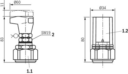
| 1.1 | Adjustment type "1" |
| 1.2 | Adjustment type "2" |
| 2 | Lock nut, tightening torque MA = 10+5 Nm |
Information
General information:
- The unloading function (directional valve function with version "W") must not be used for safety functions.
- With version "B", the lowest adjustable pressure (circulation pressure) is set in case of power failure or cable break. With version "A", the pressure limiting function is set in case of power failure or cable break.
- Hydraulic counter pressures in port T with internal pilot oil return and/or port Y with external pilot oil return add 1:1 to the response pressure of the valve set at the pilot control.
Example:- Pressure adjustment of the valve by spring preload (item 7 "Product description") in the pilot control valve/adjustment type pspring = 200 bar
- Hydraulic counter pressure in port T with internal pilot oil return phydraulic = 50 bar
- => Response pressure = pspring + phydraulic = 250 bar
Accessories
Mating connectors for valves with connector “K4”, without circuitry, standard
3P Z4

Mating connectors for valves with connector “K4”, without circuitry, standard
3P Z4
- For valves with connector “K4” according to EN 175301-803 and ISO 4400, 2-pole + PE, “large cubic connector”
- Mating connectors for valves with one or two solenoids (individual connection)
Mating connectors for valves with connector “K4”, with indicator light
3P Z5L

Mating connectors for valves with connector “K4”, with indicator light
3P Z5L
- For valves with connector “K4” according to EN 175301-803 and ISO 4400, 2-pole + PE, “large cubic connector”
- Mating connectors for valves with one or two solenoids (individual connection)
Mating connectors for valves with connector “K4”, with indicator light and Zener diode suppression circuit
3P Z5L1

Mating connectors for valves with connector “K4”, with indicator light and Zener diode suppression circuit
3P Z5L1
- For valves with connector “K4” according to EN 175301-803 and ISO 4400, 2-pole + PE, “large cubic connector”
- Mating connectors for valves with one or two solenoids (individual connection)
Mating connectors for valves with connector “K4”, with rectifier
3P RZ5

Mating connectors for valves with connector “K4”, with rectifier
3P RZ5
- For valves with connector “K4” according to EN 175301-803 and ISO 4400, 2-pole + PE, “large cubic connector”
- Mating connectors for valves with one or two solenoids (individual connection)
Safety Instructions
Type-examination tested safety valves, version "E"
(Component series 3X, according to the Pressure Equipment Directive 2014/68/EU)
- Before ordering a type-examination tested safety valve, it must be observed that for the desired response overpressure p the maximum admissible flow qV max of the safety valve must be larger than the maximum possible flow of the system.
- According to Pressure Equipment Directive 2014/68/EU, the increase of the system pressure by the flow must not be higher than 10 % of the set response pressure (see component marking).
- Discharge lines (ports T and Y) of safety valves must end in a risk-free manner. The accumulation of fluids in the discharge lines must not be possible (AD 2000 - data sheet A 2).
- If a lead seal at the safety valve is removed, the approval according to the PED.
- Basically, the requirements of the Pressure Equipment Directive 2014/68/EU and of AD 2000 - data sheet A 2 have to be observed.
Always observe the application notes:
- In the plant, the response pressure specified in the component marking is set with a flow of 12 l/min (version "Y" with 9 l/min).
- The maximum admissible flow stated in the component marking (= numerical value instead of the character "G" in the component marking) must not be exceeded. It applies to:
- Pilot oil return external ("Y") without counter pressure in the discharge line Y; admissible counter pressure in the discharge line (port T) < 15 bar
- Pilot oil return internal ("no code"). The maximum flow is only admissible without counter pressure in the discharge line (port T).
With internal pilot oil return, the system pressure increases by the counter pressure in the discharge line (port T) with increasing flow (observe AD2000 - data sheet A2 - item 6.3).
To ensure that this increase in system pressure caused by the flow does not exceed 10 % of the set response pressure, the admissible flow has to be reduced dependent on the counter pressure in the discharge line (port T) (see "Diagrams/Characteristic curves").
Notice:
Possible unloading via the directional valve must not be applied for safety-relevant functions. If unloading is required for safety-relevant functions, an additional safety valve must be installed.
Downloads
| Pressure relief valve, pilot-operated Data Sheet | RE25850 | 2021-10-01 | English, United States | PDF | 757k Product Groups: Pressure relief valves Type DB; DBW | |
| Pressure relief valve, pilot-operated Manual | RE25850-B | 2021-10-01 | English | PDF | 1.3MB Product Groups: Industrial Hydraulics Type DB(W)52...3X/..E |


Нет отзывов об этом товаре.