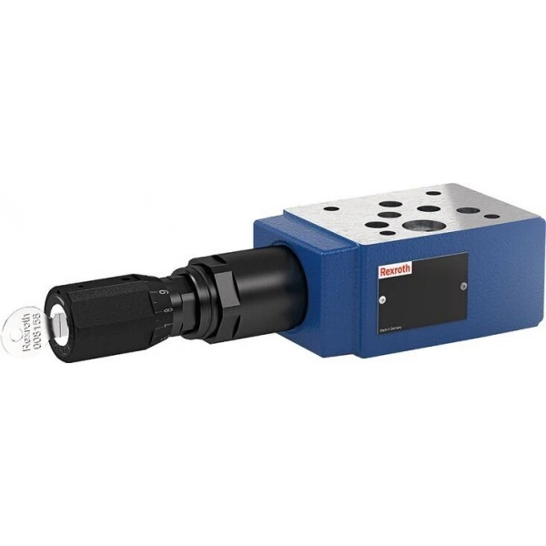
Артикул: RX7487
В наличии
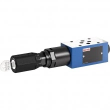
Pressure reducing valve, pilot-operated Z3DR 10
Цена по запросу Стоимость зависит от выбранного способа оплаты и количества товара.
Не отвечаем 5 минут — скидка на весь заказ!
Нужна скидка? Звони — сделаем лучшее предложение
Работаем по всей России
Возможны самовывоз и доставка по всей территории России
Надежность
Профессиональная поддержка
Description
- Size 10
- Component series 1X
- Maximum operating pressure 350 bar
- Maximum flow 120 l/min
- Size 10
- Component series 1X
- Maximum flow 120 l/min
Features
- Sandwich plate valve
- Porting pattern according to ISO 4401-05-04-0-05 (standard version) or ISO 4401-05-05-0-05 (version "SO30")
- 4 pressure ratings, optional
- 2 adjustment types, optionally:
• Spindle with internal hexagon and protective cap
• Lockable rotary knob with scale - Corrosion-protected design
Product description
Valves of type Z3DR are pilot-operated 3-way pressure reducing valves with pressure limitation of the actuator in sandwich plate design. They serve for reduction and control of the system pressure.
The valves basically consist of pilot control valve (1) and housing (2) including main stage. The secondary pressure is set via the adjustment type (3).
Rexroth pilot-operated pressure reducing valves feature high stability and low hysteresis.
Version "MS" enables measurement and monitoring of the set secondary pressure via a pressure load cell at the measuring port (4) (refer to Dimensions).
If the secondary pressure at actuator port P① (A②, B②) further exceeds the set value, the third line to tank port TA (TB) is opened by the valve. In this way, the actuator channel is protected against inadmissible pressure rise.
Type Z3DR 10 VP…
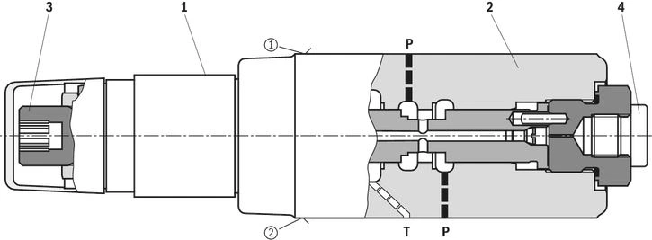
| ① | component side |
| ② | plate side |
Type code
| 01 | 02 | 03 | 04 | 05 | 06 | 07 | 08 | 09 | 10 | 11 | 12 | 13 | ||
| Z | 3 | DR | 10 | V | - | 1X | / |
| 01 | Sandwich plate valve | Z |
| 02 | 3-way version | 3 |
| 03 | Pressure reducing valve | DR |
| 04 | Size 10 | 10 |
| 05 | Pilot-operated | V |
| Pressure reduction | ||
| 06 | In channel P ① | P |
| In channel A ② | A | |
| In channel B ② | B | |
| Adjustment type | ||
| 07 | Spindle with internal hexagon and protective cap ("J3" version without protective cap) | 2 |
| Lockable rotary knob with scale 1) | 3 | |
| 08 | Component series 10 ... 19 (10 ... 19: unchanged installation and connection dimensions) | 1X |
| Pressure rating | ||
| 09 | Set pressure up to 50 bar | 50 |
| Set pressure up to 100 bar | 100 | |
| Set pressure up to 200 bar | 200 | |
| Set pressure up to 315 bar | 315 | |
| Pressure measuring port | ||
| 10 | Without pressure measuring port | no code |
| With pressure measuring port (secondary pressure) | MS | |
| Corrosion resistance | ||
| 11 | None | no code |
| Improved corrosion protection (240 h salt spray test according to EN ISO 9227); (only version "2") | J3 | |
| Seal material | ||
| 12 | NBR seals | no code |
| FKM seals | V | |
| Observe compatibility of seals with hydraulic fluid used. | ||
| Pilot oil duct | ||
| 13 | None | no code |
| Via channel X and Y | SO30 | |
| 1) | H-Key with material no. R900008158 is included in the scope of delivery. |
Notice:
For valve types for use in explosive areas, refer to data sheet 07011.
Technical data
general
| Size | 10 | ||
| Weight | Version "2" | kg | 2.7 |
| Version "3" | kg | 2.8 | |
| Installation position | any | ||
| Ambient temperature range | °C | -20 … +80 | |
hydraulic
| Size | 10 | |||
| Maximum operating pressure | Port B | bar | 350 | |
| Port P | bar | 350 | ||
| Maximum return flow pressure 1) | Port T | bar | 160 | |
| Maximum set pressure | Version | 50 | bar | 50 |
| 100 | bar | 100 | ||
| 200 | bar | 200 | ||
| 315 | bar | 315 | ||
| Minimum adjustable secondary pressure | bar | 12 | ||
| Maximum flow 2) | l/min | 120 | ||
| Hydraulic fluid | see table | |||
| Hydraulic fluid temperature range | °C | -20 … +80 | ||
| Viscosity range 3) | mm²/s | 10 … 500 | ||
| Maximum admissible degree of contamination of the hydraulic fluid 4) | Class 20/18/15 according to ISO 4406 (c) | |||
| 1) | Ideally depressurized to the tank. Counter pressure adds to the set pressure. |
| 2) | Recommended |
| 3) | Preferably 50 … 120 mm2/s |
| 4) | The cleanliness classes specified for the components must be adhered to in hydraulic systems. Effective filtration prevents faults and simultaneously increases the life cycle of the components. For the selection of the filters, see www.boschrexroth.com/filter. |
| Hydraulic fluid | Classification | Suitable sealing materials | Standards | Data sheet | |
| Mineral oils | HL, HLP | NBR, FKM | DIN 51524 | 90220 | |
| Bio-degradable 1) | Insoluble in water | HETG | FKM | ISO 15380 | 90221 |
| HEES | FKM | ||||
| Soluble in water | HEPG | FKM | ISO 15380 | ||
| Flame-resistant | Water-free | HFDU (glycol base) | FKM | ISO 12922 | 90222 |
| HFDU (ester base) 1) | FKM | ||||
| Containing water | HFC (Fuchs Hydrotherm 46M, Petrofer Ultra Safe 620) | NBR | ISO 12922 | 90223 | |
| Important information on hydraulic fluids:
| |||||
| 1) | Not recommended for corrosion-protected version “J3” |
(For applications outside these values, please consult us!)
Diagrams/characteristic curves
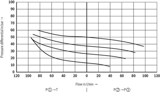
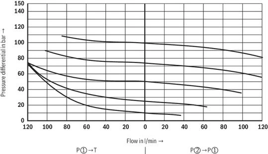
(measured with HLP46, ϑOil = 40 ±5 °C)
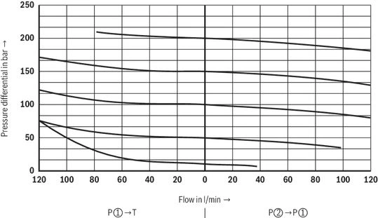
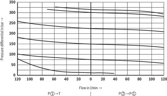
Δp-qV characteristic curves
Pressure rating 50 bar
Pressure rating 100 bar
Pressure rating 200 bar
Pressure rating 315 bar
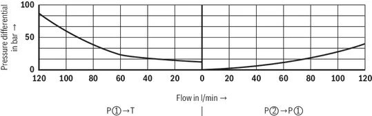
Δp-qV characteristic curves
Symbols/Circuit diagrams
Version "P…MS..SO30"
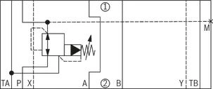
Version "B…MS..SO30"
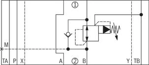
Version "A…MS..SO30"
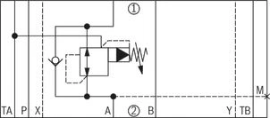
| ① | component side |
| ② | plate side |
Notice:
- Deviating from ISO 4401, port T is called TA and port T1 is called TB in this data sheet.
- Version "MS" is shown. With the standard version, port M is omitted.
- Version "SO30" is shown. The standard version does not have ports X and Y.
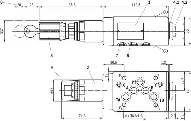
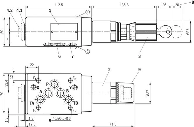
Dimensions
Version "P" and "A"
Dimensions in mm
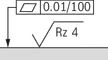 |
| Required surface quality of the valve contact surface |
| ① | component side – Porting pattern according to ISO 4401-05-04-0-05 (standard version) or ISO 4401-05-05-0-05 (“SO30” version) |
| ② | plate side – Porting pattern according to ISO 4401-05-04-0-05 (standard version) or ISO 4401-05-05-0-05 (version “SO30”) |
| 1 | Name plate |
| 2 | Adjustment type "2" (spindle with internal hexagon SW8 and lock nut SW24) |
| 3 | Adjustment type "3" |
| 4.1 | Without measuring port (standard) |
| 4.2 | Measuring port (version "MS"); when loosening the plug screw (SW6 internal hexagon, tightening torque MA = 30 Nm ±10 %), hold the SW27 reducing piece in place |
| 5 | Valve mounting bores |
| 6 | Identical seal rings for ports A, B, P and T (plate side) |
| 7 | Identical seal rings for ports X and Y (plate side) |
| 8 | Space required to remove the key |
| 9 | Protective cap (not included with version "J3") |
Valve mounting screws (separate order)
4 hexagon socket head cap screws ISO 4762 - M5 - 10.9
Notes:
- Length and tightening torque of the valve mounting screws must be calculated according to the components mounted under and over the sandwich plate valve.
- Deviating from ISO 4401, port T is called TA and port T1 is called TB in this data sheet.
- The dimensions are nominal dimensions which are subject to tolerances.
- Version "SO30" is shown. The standard version does not have ports X and Y.
Version "B"
Dimensions in mm
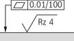 |
| Required surface quality of the valve contact surface |
| ① | component side – Porting pattern according to ISO 4401-05-04-0-05 (standard version) or ISO 4401-05-05-0-05 (“SO30” version) |
| ② | plate side – Porting pattern according to ISO 4401-05-04-0-05 (standard version) or ISO 4401-05-05-0-05 (version “SO30”) |
| 1 | Name plate |
| 2 | Adjustment type "2" (spindle with internal hexagon SW8 and lock nut SW24) |
| 3 | Adjustment type "3" |
| 4.1 | Without measuring port (standard) |
| 4.2 | Measuring port (version "MS"); when loosening the plug screw (SW6 internal hexagon, tightening torque MA = 30 Nm ±10 %), hold the SW27 reducing piece in place |
| 5 | Valve mounting bores |
| 6 | Identical seal rings for ports A, B, P and T (plate side) |
| 7 | Identical seal rings for ports X and Y (plate side) |
| 8 | Space required to remove the key |
| 9 | Protective cap (not included with version "J3") |
Valve mounting screws (separate order)
4 hexagon socket head cap screws ISO 4762 - M5 - 10.9
Notes:
- Length and tightening torque of the valve mounting screws must be calculated according to the components mounted under and over the sandwich plate valve.
- Deviating from ISO 4401, port T is called TA and port T1 is called TB in this data sheet.
- The dimensions are nominal dimensions which are subject to tolerances.
- Version "SO30" is shown. The standard version does not have ports X and Y.
Accessories
| Denomination | Material number |
| Protective cap | R900135501 |
Downloads
 | Pressure reducing valve, pilot-operated Data Sheet | RE26874 | 2016-10-01 | English | PDF | 509k Product Groups: Pilot operated Type Z3DR |
Отзывы о товаре
Официальный поставщик Bosch Rexroth
Продажи на территории России
Оптовые и розничные продажи
Снижение логистических расходов
Индивидуальные условия
Выгода без посредников
Единая система поставок
Весь ассортимент на складе