
Артикул: RX7471
Directional spool valves, direct operated, with solenoid actuation Z4WE 6
Доступно к заказу
Цена по запросу
И выбери подходящего.
Description
- Size 6
- Component series 3X
- Maximum operating pressure 315 bar
- Maximum flow 50 l/min
Features
- 4/2 and 4/3 directional shut-off valve
- Sandwich plate valve
- As straight-through valve or short-circuit valve
- Porting pattern according to ISO 4401-03-02-0-05 (with or without locating hole)
- Wet-pin AC or DC solenoids
- Use optionally with PWM connector (fast switching amplifier, energy reduction)
- Optional auxiliary operating device
- Spool position monitoring, optional
- CE conformity according to the Low-Voltage Directive 2014/35/EU for electrical voltages >50 VAC or >75VDC
Product description
The directional valves type Z4WE are solenoid-actuated directional spool valves. They control start, stop and direction of a flow.
The directional valves basically consist of the housing (1), one or two solenoids (2), the control spool (3), and two return springs (4).
In de-energized condition, the control spool (3) is held in the central position or in the initial position by the return springs (4). The control spool (3) is actuated by wet-pin solenoids (2).
The hydraulic system must be properly bled to ensure proper function.
The force of the solenoid (2) acts via the plunger (5) on the control spool (3) and pushes the latter from its rest position to the required end position. This opens up the required direction of flow A② to A① and B② to B①.
After de-excitation of the solenoid (2), the return spring (4) pushes the control spool (3) back to its rest position.
An optional manual override (6) allows the control spool (3) to be moved without solenoid energization.
Notice:
Due to the design principle, internal leakage is inherent to the valves, which may increase over the life cycle.
For admissible shock and vibration loads, see data sheet 08012.
Type Z4WE 6…

| ① | component side |
| ② | plate side |
Type code
| 01 | 02 | 03 | 04 | 05 | 06 | 07 | 08 | 09 | 10 | 11 | 12 | 13 | 14 | ||
| Z4WE | 6 | ‒ | 3X | / | E | K4 | * |
| 01 | Shut-off valve, sandwich plate design | ZW4E |
| 02 | Size 6 | 6 |
| 03 | Symbols; for the possible version, see "Symbols/Circuit diagrams" | |
| 04 | Component series 30 ... 39 (30 ... 39: unchanged installation and connection dimensions) | 3X |
| 05 | High-power solenoid, wet-pin, with detachable coil | E |
| Electrical voltages | ||
| 06 | For ordering code see "Electrical connections and available voltages" below. | e.g. G24 |
| Manual override 1) | ||
| 07 | Without manual override | no code |
| With lockable manual override "mushroom button" (small) | N4 2) | |
| With lockable manual override "mushroom button" (large) | N5 2) | |
| With concealed manual override (standard) | N9 2) | |
| Electrical connection | ||
| 08 | Without mating connector, with connector DIN EN 175301-803 | K4 3) |
| Without mating connector, with connector DIN EN 175301-803 Coil with potted-in connector base and sealing element to valve housing (IP67) | K4K 3; 4) | |
| Spool position monitoring (For more information, see data sheet 24830) | ||
| 09 | Without position switch | no code |
| Monitored spool position "a" | QMAG24 | |
| Monitored spool position "b" | QMBG24 | |
| Monitored rest position | QM0G24 | |
| Seal material (observe compatibility of seals with hydraulic fluid used, see "Technical data") | ||
| 10 | NBR seals | no code |
| FKM seals | V | |
| Recommended for operation with HFC hydraulic fluids | MH | |
| 11 | Without locating hole | no code |
| With locating hole and locking pin ISO 8752-3x8-St | /62 | |
| 12 | Standard | no code |
| Approval according to CSA C22.2 no. 139-1982 | = CSA | |
| 13 | Standard | no code |
| DC or AC voltage (symbols "E…") | ||
| Special housing with connection A①–B① (in housing and control spool); symbol "E147" only | SO10 | |
| Orifice function Ø0,6 mm | SO742 | |
| Orifice function Ø0,8 mm | SO744 | |
| Orifice function Ø0,9 mm | SO749 | |
| Orifice function Ø1,2 mm | SO746 | |
| Orifice function Ø1,3 mm | SO747 | |
| Orifice function Ø1,45 mm | SO65 | |
| Orifice function Ø1,5 mm | SO748 | |
| Control spool with integrated orifice Ø1,2 mm. Coil rotated by 180°. The electrical connection of the coil points in direction T. | SO765 | |
| DC voltage (symbols "X…") | ||
| Special housing with orifice Ø2.0 mm between P and working port as well as Ø2.0 mm between working port and T. The electrical connection of the coil points in direction T. | SO60 | |
| Special housing with orifice Ø0.8 mm between P and working port as well as Ø0.8 mm between working port and T. The electrical connection of the coil points in direction T. | SO61 | |
| Special housing with orifice Ø1.3 mm between P and working port as well as Ø2.0 mm between working port and T. The electrical connection of the coil points in direction T. | SO64 | |
| Control spool with integrated orifice Ø0.6 mm between A① and B① as well as orifice Ø1.3 mm between A② and B②; symbol "X258" only | SO63 | |
| 14 | Further details in the plain text | * |
| 1) | The manual override cannot be allocated a safety function. It may only be used up to a tank pressure of 50 bar. |
| 2) | DC voltage only |
| 3) | Mating connectors, separate order, see "Accessories" and datasheet 08006. |
| 4) | With additional sealing between solenoid coil and housing. |
Electrical connections and available voltages
(special voltages upon request)
DC voltage – individual connection
| Connector | Ordering code | Electrical voltages | Protection class according to EN 60529 1) | Protection class according to VDE 0580 | |||||||||
| 12 V | 24 V | 26 V | 48 V | 96 V | 110 V | 125 V | 205 V | 220 V | |||||
| Ordering code | |||||||||||||
| G12 | G24 | G26 | G48 | G96 | G110 | G125 | G205 | G220 | |||||
| 3-pole connector (2+PE) according to DIN EN 175301-803 |
| K4 | ✔ | ✔ | - | ✔ | ✔ | ✔ | ✔ | ✔ | ✔ | IP65 | I 2) |
| K4K | ✔ | ✔ | ✔ | - | - | - | - | - | - | IP65 | I 2) | |
| Maximum admissible overvoltages according to DIN EN 60664-1:2008-01 (VDE 0110-1) (overvoltage category II): | |||||||||||||
| Nominal voltage UNom | V | 12 | 24 | 26 | 48 | 96 | 110 | 125 | 205 | 220 | |||
| Rated current INom | A | 2,5 | 1,25 | 1,17 | 0,66 | 0,33 | 0,25 | 0,17 | 0,16 | 0,14 | |||
| Maximum admissible switch-off overvoltage according to VDE 0580 | V | 500 | 500 | 500 | 500 | 500 | 500 | 500 | 500 | 500 | |||
| Recommended interference protection circuit with 2 x mains voltage | V | 24 | 48 | 52 | 96 | 192 | 220 | 250 | 410 | 440 | |||
| 1) | Only with correctly mounted valve with a mating connector suitable for the protection class. |
| 2) | Protection class I with properly connected protective grounding conductor (PE) and valve mounting surface connected to the protective grounding conductor system. |
| 3) | With protection class III, a protective extra-low voltage with isolation transformer (PELV, SELV) is to be provided. |
Notice:
Solenoid valves induce voltage peaks during switch-off. In order to prevent electro-magnetic interference at the system and damage to the valve control, an interference protection circuit has to be provided on the system side. Alternatively, you can also select a connector with integrated interference protection circuit.
Alternating voltage – individual connection
| Connector | Ordering code | Electrical voltages | Protection class according to EN 60529 1) | Protection class according to VDE 0580 | ||||||||||
| 100 V 50/60 Hz | 100 V 50/60 Hz | 110 V 50/60 Hz | 110 V 50/60 Hz | 120 V 60 Hz | 120 V 60 Hz | 200 V 50 Hz | 200 V 50 Hz | 230 V 50/60 Hz | 230 V 50/60 Hz | |||||
| Ordering code | ||||||||||||||
| G96 | W100 | G96 | W110 | G110 | W110 | G180 | W200 | G205 | W230 | |||||
| 3-pole connector (2+PE) according to DIN EN 175301-803 | Standard | K4 | ✔ | ✔ | ✔ | ✔ | ✔ | ✔ | ✔ | ✔ | ✔ | ✔ | IP65 | I 2) |
| Rectifier required (see "Accessories") | ✔ | - | ✔ | - | ✔ | - | ✔ | - | ✔ | - | ||||
| Maximum admissible overvoltages according to DIN EN 60664-1:2008-01 (VDE 0110-1) (overvoltage category II): | ||||||||||||||
| Nominal voltage UNom | V | 100 | 100 | 110 | 110 | 120 | 120 | 200 | 200 | 230 | 230 | |||
| Rated current INom |
| A | 0,31 | 0,56 | 0,34 | 0,52 | - | - | 0,18 | 0,29 | 0,16 | 0,23 | ||
| A | 0,31 | 0,44 | 0,34 | 0,39 | 0,30 | 0,45 | - | - | 0,16 | 0,17 | |||
| Lower rated current |
| A | - | 0,65 | - | 0,6 | - | - | - | 0,33 | - | 0,27 | ||
| A | - | 0,51 | - | 0,45 | - | 0,52 | - | - | - | 0,2 | |||
| Upper rated current |
| A | - | 0,9 | - | 0,9 | - | - | - | 0,6 | - | 0,36 | ||
| A | - | 0,9 | - | 0,6 | - | 0,9 | - | - | - | 0,36 | |||
| Maximum admissible switch-off overvoltage according to VDE 0580 | V | 500 | 500 | 500 | 500 | 500 | 500 | 500 | 500 | 500 | 500 | |||
| Recommended interference protection circuit with 2 x mains voltage | V | 200 | 200 | 220 | 220 | 240 | 240 | 400 | 400 | 460 | 460 | |||
| 1) | Only with correctly mounted valve with a mating connector suitable for the protection class. |
| 2) | Protection class I with properly connected protective grounding conductor (PE) and valve mounting surface connected to the protective grounding conductor system. |
Notices:
- Solenoid valves induce voltage peaks during switch-off. In order to prevent electro-magnetic interference at the system and damage to the valve control, an interference protection circuit has to be provided on the system side. Alternatively, you can also select a connector with integrated interference protection circuit.
- Depending on the rated current INom, circuit breakers according to tripping characteristic "K" are to be provided.
The tripping current must lie within a time interval of 0.6 s with 8 to 10 times the nominal power supply.
The required non-tripping current of the fuse must not fall below the "lower rated current" value (see preceding table). The maximum tripping current must not exceed the "upper rated current" value (see preceding table).
The temperature dependence of the tripping behavior of the circuit breakers has to be considered according to the manufacturer's specifications.
Technical data
(For applications outside these values, please consult us!)
general
| Size | 6 | ||
| Weight | Valve with one solenoid | kg | 1.2 |
| Valve with two solenoids | kg | 1.6 | |
| Installation position | any (with suspended installation, higher sensitivity to contamination; horizontal installation is recommended) | ||
| Ambient temperature range | NBR seals | °C | -20 … +50 |
| FKM seals | °C | -15 … +50 | |
| Storage temperature range | °C | +5 … +40 | |
| MTTFD values according to EN ISO 13849 1) | Years | 150 | |
| Admissible shock and vibration loads | see data sheet 08012 | ||
| 1) | For further details, see data sheet 08012 |
hydraulic
| Size | 6 | |||
| Maximum operating pressure | Port P | bar | 315 | |
| Anschluss A | bar | 315 | ||
| Port B | bar | 315 | ||
| Port T | Direct voltage | bar | 210 | |
| AC voltage | bar | 160 | ||
| Maximum flow | l/min | 50 | ||
| Hydraulic fluid | see table "Hydraulic fluid" | |||
| Hydraulic fluid temperature range (at the valve working ports) | NBR seals | °C | -30 … +80 | |
| FKM seals | °C | -20 … +80 | ||
| Seals for HFC hydraulic fluid | °C | -20 … +50 | ||
| Viscosity range | mm²/s | 2.8 … 500 | ||
| Maximum admissible degree of contamination of the hydraulic fluid, cleanliness class according to ISO 4406 (c) 1) | Class 20/18/15 | |||
| 1) | The cleanliness classes specified for the components must be adhered to in hydraulic systems. Effective filtration prevents faults and simultaneously increases the life cycle of the components. For the selection of the filters, see www.boschrexroth.com/filter. |
| Hydraulic fluid | Classification | Suitable sealing materials | Standards | Data sheet | |
| Mineral oils | HL, HLP, HLPD, HVLP, HVLPD | NBR, FKM | DIN 51524 | 90220 | |
| Bio-degradable | Insoluble in water | HETG | FKM | ISO 15380 | 90221 |
| HEES | FKM | ||||
| Soluble in water | HEPG | FKM | ISO 15380 | ||
| Flame-resistant | Water-free | HFDU (glycol base) | FKM | ISO 12922 | 90222 |
| HFDU (ester base) | FKM | ||||
| HFDR | FKM | ||||
| Containing water | HFC (Fuchs: Hydrotherm 46M, Renosafe 500; | NBR | ISO 12922 | 90223 | |
| Important information on hydraulic fluids:
| |||||
electrical
| Voltage type | Direct voltage | AC voltage 50/60 Hz | ||
| Nominal voltage according to VDE 0580 1) | See "Type codes" | |||
| Voltage tolerance (nominal voltage) | % | ± 10 | ||
| Power consumption 2) | W | 30 | - | |
| Holding power | VA | - | 50 | |
| Switch-on power | VA | - | 220 | |
| Duty cycle | 100% (S1 according to VDE 0580) | |||
| Switching time according to ISO 6403 3) | ON | ms | 20 … 45 | 10 … 20 |
| OFF | ms | 10 … 25 | 15 … 40 | |
| Maximum switching frequency | 1/h | 15000 | 7200 | |
| Maximum surface temperature of the coil 4) | °C | 120 | ||
| Protection class according to EN 60529 | See "Type codes" | |||
| Insulation class VDE 0580 | See "Type codes" | |||
| Electrical fuse protection | Maximum admissible switch-off overvoltage see "Type codes". Every solenoid must be protected individually, using a suitable fuse with tripping characteristics K (inductive loads). | |||
| Protective earthing conductor and screening | The valve must be installed on a surface that is included in the equipotential bonding. Connector pin assignment (CE-compliant installation) see "Electrical connection". | |||
| Conformity | CE according to Low-Voltage Directive 2014/35/EU checked according to EN 60204-1:2006-01 and DIN VDE 0580, classified as component. | |||
| 1) | Special voltages available upon request |
| 2) | Reduction of the nominal power by approx. 40 % when using a 24 V coil with connector switching amplifier type VT-SSBA1-PWM-1X/V002/5 (separate order, material no. R901290194, see data sheet 30362) |
| 3) | Measured without flow. The switching times were determined for a hydraulic fluid temperature of 40 °C and a viscosity of 46 mm2/s. Switching times change dependent on hydraulic fluid temperatures, operating time and application conditions. |
| 4) | Due to the temperatures occurring at the surfaces of the solenoid coils, the standards ISO 13732-1 and ISO 4413 need to be adhered to!The specified surface temperature in AC solenoids is valid for fault-free operation. In the error case (e.g. blocking of the control spool), the surface temperature may increase above 180 °C. Thus, the system must be checked for possible dangers considering the ignition temperature of the hydraulic fluid used. As fuse protection, circuit breakers must be used, unless the creation of an ignitable atmosphere can be excluded in a different way. In this way, the surface temperature in an error case can be limited to a maximum of 220 °C. You have to use cables that have been approved of for a working temperature of more than 50 °C (individual connection) and/or 90 °C (central connection). |
Notices:
- Actuation of the manual override is only possible up to a tank pressure of approx. 50 bar. Avoid damage to the bore of the manual override. (Special tool for the operation, separate order, material no. R900024943). When the manual override is blocked, the operation of the solenoid must be prevented.
- Simultaneous actuation of the solenoids must be prevented.
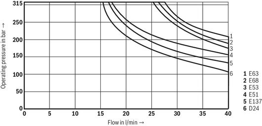
Diagrams/characteristic curves
(measured with HLP46, ϑOil = 40 ±5 °C)
Δp-qV characteristic curves
DC or AC voltage (symbols "E…")

| Symbol | A➁‒A➀ | A➀‒A➁ | B➁‒B➀ | B➀‒B➁ | A➁‒B➁ | B➁‒A➁ | T➁‒T➀ | P➁‒P➀ |
| D24 | 4 | 1 | 2 | 4 | 3 | 2 | 7 | 7 |
| E51 | 3 | 1 | 1 | 3 | ‒ | ‒ | 7 | 7 |
| E53 | 2 | 2 | 2 | 2 | 5 | 2 | 7 | 7 |
| E63 | 2 | 5 | 5 | 3 | ‒ | ‒ | 7 | 7 |
| E68 | 4 | 4 | 6 | 5 | 4 | 5 | 7 | 7 |
| E137 | 1 | 4 | 3 | 2 | 5 | 6 | 7 | 7 |
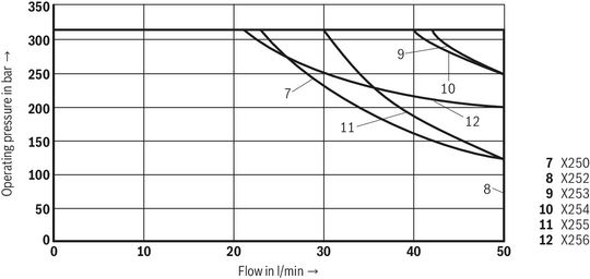
Δp-qV characteristic curves
DC voltage (symbols "X…")

| Symbol | Spool position | A➀‒A➁ A➁‒A➀ | B➀‒B➁ | B➁‒B➀ | T➁‒T➀ | P➁‒P➀ | P➀‒T➁ | B➁‒T➁ | P➁‒P➀ | A➁‒T➁ | P➁‒A➁ B➁‒T➁ |
| X250 | 16 | 17 | 17 | 18 | 13 | 10 | ‒ | ‒ | ‒ | ‒ | |
| X252 | 16 | 17 | 17 | 18 | 9 | 11 | ‒ | ‒ | ‒ | ‒ | |
| X253 | 13 | 14 | 14 | 19 | 18 | ‒ | ‒ | ‒ | 8 | ‒ | |
| X254 | 16 | 12 | 13 | 18 | 18 | ‒ | 12 | ‒ | ‒ | ‒ | |
| X255 | 0 | ‒ | ‒ | ‒ | 15 | ‒ | ‒ | 8 | ‒ | 8 | ‒ |
| a | 12 | ‒ | ‒ | ‒ | ‒ | ‒ | 13 | ‒ | ‒ | ‒ | |
| b | ‒ | 12 | 12 | ‒ | ‒ | ‒ | ‒ | ‒ | 13 | ‒ | |
| X256 | 12 | 9 | 9 | 18 | ‒ | ‒ | ‒ | 18 | ‒ | 20 |
Power limit
(measured with HLP46, ϑOil = 40 ±5 °C and 24 V DC voltage)
Power limit
(measured with HLP46, ϑOil = 40 ±5 °C and 230 V AC voltage)

| Symbol | W230 50 Hz | W230 60 Hz |
| E63 | 13 | 16 |
| E68 | 14 | 18 |
| E53 | 15 | 18 |
| E137 | 17 | 17 |
| E51 | 17 | 17 |
| D24 | 17 | 17 |
Notice:
The specified performance limits are valid for operation with two directions of flow (e.g. from P to A and simultaneous return flow from B to T).
Due to the flow forces acting within the valves, the possible performance limit may be considerably lower with only one direction of flow (e.g. from P to A while port B is blocked).
The performance limits were determined when the solenoids were at operating temperature, at 10% undervoltage and without tank preloading.
Symbols/Circuit diagrams
DC or AC voltage (① = component side, ② = plate side)
| Symbol | Interim positions | Notices | |
| D24 |  |  | – |
| D27 |  |  | – |
| E51 |  |  | – |
| E53 |  |  | – |
| E56 |  |  | – |
| E62 |  |  | – |
| E63 |  |  | – |
| E68 |  |  | – |
| E127 |  |  | – |
| E130 |  |  | – |
| E131 |  |  | – |
| E132 |  |  | – |
| E135 |  |  | Only possible with SO number, see "Ordering code". |
| E136 |  |  | Function with orifice Ø1.3 mm |
| E137 |  |  | Function with orifice Ø1.7 mm |
| E138 |  |  | Only possible with SO number, see "Ordering code". |
| E140 |  |  | Only possible with SO number, see "Ordering code". |
| E144 |  |  | – |
| E145 |  |  | – |
| E146 |  |  | – |
| E147 |  |  | Only possible with version "SO10", see "Ordering code". |
| E166 |  |  | – |
Notice:
Representation according to ISO 1219-1.
Hydraulic interim positions are shown by dashes.
Direct voltage (① = component side, ② = plate side)
| Symbol | Interim positions | Notices | |
| X161 |  |  | Only possible with SO number, see "Ordering code". |
| X163 |  |  | Only possible with SO number, see "Ordering code". |
| X181 |  |  | Only possible with SO number, see "Ordering code". |
| X183 |  |  | Only possible with SO number, see "Ordering code". |
| X250 |  |  | – |
| X252 |  |  | – |
| X253 |  |  | – |
| X254 |  |  | – |
| X255 |  |  | – |
| X256 |  |  | Function with orifice Ø1.4 mm |
| X257 |  |  | – |
| X258 |  |  | Only possible with version "SO63", see "Ordering code". |
| X259 |  |  | – |
Notice:
Representation according to ISO 1219-1.
Hydraulic interim positions are shown by dashes.
Electrical connection
Electrical connections, assignment – individual connection
| Ordering code connector | Top view | Circuit diagram | Pin | Connections, assignment | |
| 3-pole connector (2+PE) according to DIN EN 175301-803 | K4 |  |  | 1 | Solenoid coil, polarity-independe |
| 2 | |||||
| 3-pole connector (2+PE) according to DIN EN 175301-803 (with potted-in plug base and sealing element) | K4K 1) |  | Earthing | ||
| 1) | Coil with potted-in connector base and sealing element to valve housing (IP67) |
Notices:
- When establishing the electrical connection, the protective grounding conductor (PE) must be connected correctly.
- Electric lines must be routed in a strain-relieved manner.
- Cable glands are only suitable for permanently installed cables.
- Connectors are to be locked during operation. Not intended to be plugged in or disconnected during normal operation under load.
- Protective grounding conductor cross-section equal to or greater than the line cross-section of the voltage supply.
- The valve mounting surface must be connected to the protective grounding conductor system.
Dimensions
Direct voltage
Symbols D24, E51, E53, E63, E68, E137, …
Dimensions in mm

 |
| Required surface quality of the valve contact surface |
| ➀ | component side – porting pattern according to ISO 4401-03-02-0-05 (with or without locating hole); (with locating hole Ø3 x 5 mm deep) |
| ➁ | plate side – porting pattern according to ISO 4401-03-02-0-05 (with locating hole for locking pin ISO 8752-3x8-St; version "/62") |
| 3 | Locking pin ISO 8752-3x8-St (only version "/62") |
| 4 | Dimension for solenoid with concealed manual override "N9" (standard) and for valve without manual override |
| 7 | Mating connector without circuitry for connector "K4", separate order, see "Accessories" |
| 8 | Mating connector with circuitry for “K4” connector, separate order, see "Accessories" |
| 9 | Space required to remove the mating connector |
| 10 | Identical seal rings for ports A, B, P, T (plate side) |
| 11 | Name plate |
| 12 | Plug screw for valve with one solenoid |
Notice:
The dimensions are nominal dimensions which are subject to tolerances.
Symbols X250, X252, X253, X254, X255, X256, …
Dimensions in mm

 |
| Required surface quality of the valve contact surface |
| Symbol | Solenoid side | L1 | L2 | L3 | L4 | L5 | L6 | L7 | L8 |
| mm | mm | mm | mm | mm | mm | mm | mm | ||
| X250 | a | 25.1 | 54.9 | - | 63.3 | 93.4 | - | 215.6 | 80 |
| X252 | b | 25.1 | 54.9 | 33.5 | - | - | 123.2 | 215.6 | 80 |
| X253 | b | 18.5 | 54.3 | 26.9 | - | - | 129.8 | 215.6 | 80 |
| X254 | a | 18.5 | 54.3 | - | 69.9 | 86.8 | - | 215.6 | 80 |
| X255 | a + b | 26.1 | 53.9 | - | - | 94.4 | 131.2 | 225.4 | 90 |
| X256 | b | 12.2 | 54.8 | 20.6 | - | - | 136.1 | 225.4 | 80 |
| ➀ | component side – porting pattern according to ISO 4401-03-02-0-05 (with or without locating hole); (with locating hole Ø3 x 5 mm deep) |
| ➁ | plate side – porting pattern according to ISO 4401-03-02-0-05 (with locating hole for locking pin ISO 8752-3x8-St; version "/62") |
| 3 | Locking pin ISO 8752-3x8-St (only version "/62") |
| 4 | Dimension for solenoid with concealed manual override "N9" (standard) and for valve without manual override |
| 7 | Mating connector without circuitry for connector "K4", separate order, see "Accessories" |
| 8 | Mating connector with circuitry for “K4” connector, separate order, see "Accessories" |
| 9 | Space required to remove the mating connector |
| 10 | Identical seal rings for ports A, B, P, T (plate side) |
| 11 | Name plate |
| 12 | Plug screw for valve with one solenoid |
Notice:
The dimensions are nominal dimensions which are subject to tolerances.
DC voltage – Manual override
Dimensions in mm

| 4 | Dimension for solenoid with concealed manual override "N9" (standard) and for valve without manual override |
| 5 | Lockable manual override "mushroom button" (small) "N4" |
| 6 | Lockable manual override "mushroom button" (large) "N5" |
Notice:
The dimensions are nominal dimensions which are subject to tolerances.
AC voltage
Dimensions in mm

 |
| Required surface quality of the valve contact surface |
| ➀ | component side – porting pattern according to ISO 4401-03-02-0-05 (with or without locating hole); (with locating hole Ø3 x 5 mm deep) |
| ➁ | plate side – porting pattern according to ISO 4401-03-02-0-05 (with locating hole for locking pin ISO 8752-3x8-St; version "/62") |
| 3 | Locking pin ISO 8752-3x8-St (only version "/62") |
| 4 | Dimension for solenoid with concealed manual override "N9" (standard) and for valve without manual override |
| 7 | Mating connector without circuitry for connector "K4", separate order, see "Accessories" |
| 8 | Mating connector with circuitry for “K4” connector, separate order, see "Accessories" |
| 9 | Space required to remove the mating connector |
| 10 | Identical seal rings for ports A, B, P, T (plate side) |
| 11 | Name plate |
| 12 | Plug screw for valve with one solenoid |
Notice:
The dimensions are nominal dimensions which are subject to tolerances.
Valve mounting screws (separate order)
| Size | Quantity | Hexagon socket head cap screws |
| 6 | 4 | ISO 4762 - M5 - 10.9 (Friction coefficient μtotal = 0.09 … 0.14) Tightening torque MA = 7 Nm ±10 % |
| or | ||
| 4 | ISO 4762 - M5 - 10.9 (Friction coefficient μtotal = 0,12 … 0,17) Tightening torque MA = 8,1 Nm ±10 % | |
Notice:
Length and tightening torque of the valve mounting screws must be calculated according to the components mounted under and over the sandwich plate valve.
Accessories
Mating connectors for valves with connector “K4”, without circuitry, standard
3P Z4

Mating connectors for valves with connector “K4”, without circuitry, standard
3P Z4
- For valves with connector “K4” according to EN 175301-803 and ISO 4400, 2-pole + PE, “large cubic connector”
- Mating connectors for valves with one or two solenoids (individual connection)
Mating connectors for valves with connector “K4”, with indicator light
3P Z5L

Mating connectors for valves with connector “K4”, with indicator light
3P Z5L
- For valves with connector “K4” according to EN 175301-803 and ISO 4400, 2-pole + PE, “large cubic connector”
- Mating connectors for valves with one or two solenoids (individual connection)
Mating connectors for valves with connector “K4”, with rectifier
3P RZ5

Mating connectors for valves with connector “K4”, with rectifier
3P RZ5
- For valves with connector “K4” according to EN 175301-803 and ISO 4400, 2-pole + PE, “large cubic connector”
- Mating connectors for valves with one or two solenoids (individual connection)
Mating connectors for valves with connector “K4”, with indicator light and Zener diode suppression circuit
3P Z5L1

Mating connectors for valves with connector “K4”, with indicator light and Zener diode suppression circuit
3P Z5L1
- For valves with connector “K4” according to EN 175301-803 and ISO 4400, 2-pole + PE, “large cubic connector”
- Mating connectors for valves with one or two solenoids (individual connection)
Connector switching amplifier with pulse width modulation (PWM)
VT-SSBA1-PWM

Connector switching amplifier with pulse width modulation (PWM)
VT-SSBA1-PWM
- Component series 1X
Нет отзывов об этом товаре.