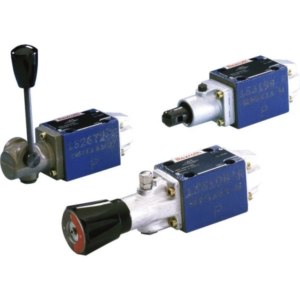
Артикул: RX7397
В наличии
Directional spool valves, direct operated, with mechanical or manual actuation WMM 6
Цена по запросу Стоимость зависит от выбранного способа оплаты и количества товара.
Не отвечаем 5 минут — скидка на весь заказ!
Нужна скидка? Звони — сделаем лучшее предложение
Работаем по всей России
Возможны самовывоз и доставка по всей территории России
Надежность
Профессиональная поддержка
Description
- Size 6
- Component series 5X
- Maximum operating pressure 315 bar
- Maximum flow 60 l/min
Features
- 4/3-, 4/2- or 3/2-way version
- Porting pattern according to DIN 24340 form A (without locating hole)
- Porting pattern according to ISO 4401-03-02-0-05 (with locating hole)
- Type of actuation: hand lever
- Inductive position switch and proximity sensors (contactless)
Product description
Type WM.. valves are mechanical, manually actuated directional spool valves. They control the start, stop and direction of a flow. Directional valves basically consist of housing (1), one type of actuation (2) (hand lever), control spool (3) and one or two return springs (4). In de-energized state, the return springs (4) maintain the control spool (3) in central or starting position - if the rotary knob is actuated with a detent. The control spool (3) is moved to the desired spool position by means of the type of actuation (2).
Detent
Directional valves with rotary knob are generally designed with detent. Directional valves with hand lever are optionally available as 2 or 3 position valves with detent. Directional valves with roller plunger are generally designed without detent. If types of actuation with detent are used, each spool position can be locked, depending on the valve type.
Throttle insert
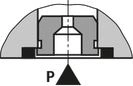
The use of a throttle insert is required when due to prevailing operating conditions, flows can occur during the switching processes, which exceed the performance limit of the valve. It is inserted in channel P of the directional valve.
Type 4WMM 6 D5X/F
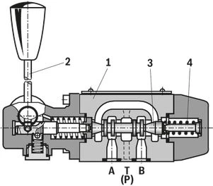
Type 4WM. 6 ..5X/..B..
Type code
| 01 | 02 | 03 | 04 | 05 | 06 | 07 | 08 | 09 | 10 | 11 | 12 | 13 | ||
| WMM | 6 | 5X | / | / | no code | * |
| 01 | 3 main ports | 3 |
| 4 main ports | 4 | |
| Type of actuation | ||
| 02 | Hand lever | WMM |
| 03 | Size 6 | 6 |
| 04 | Symbols e. g. C, E, EA, EB, etc.; for the possible version, see Symbols and Types of actuation | |
| 05 | Component series 50 … 59 (50 … 59: unchanged installation and connection dimensions) | 5X |
| 06 | With spring return | ohne Bez. |
| Without spring return with detent | F | |
| Corrosion protection | ||
| 07 | Standard corrosion protection | ohne Bez. |
| Improved corrosion protection 1) | J | |
| Spool position monitoring 2) | ||
| 08 | Without position switch | ohne Bez. |
| Inductive position switch type QM | ||
| Monitored spool position "a" | QMAG24 | |
| Monitored spool position "b" | QMBG24 | |
| Monitored rest position | QM0G24 | |
| 09 | Without throttle insert | ohne Bez. |
| Throttle Ø 0.8 mm | B083) | |
| Throttle Ø 1.0 mm | B10 3) | |
| Throttle Ø 1.2 mm | B123) | |
| Clamping length | ||
| 10 | 42 mm (standard) | no code |
| Seal material | ||
| 11 | NBR seals | ohne Bez. |
| FKM seals | V | |
| Observe compatibility of seals with hydraulic fluid used. (Other seals upon request) | ||
| 12 | Without locating hole | ohne Bez. |
| With locating hole | /604) | |
| With locating hole and locking pin ISO 8752-3x8-St | /62 | |
| 13 | Further details in the plain text | * |
| 1) The external parts made of metal are galvanized, treated with an anti-corrosion agent or made of stainless steel. This design is also suitable for on-wall applications. | |
| 2) Only for valves with 2 spool positions and versions | |
| “WMM”; not for version “J” | |
| 3) Use if flow > performance limit of the valve, effective in channel P. | |
| 4) Locking pin ISO 8752-3x8-St, material no. R900005694, separate order |
Technical data
general
| Size | 6 | ||
| Weight (approx.) | kg | 1.4 | |
| Installation position | any | ||
| Ambient temperature range | NBR seals | °C | -20 … +80 |
| FKM seals | °C | -20 … +80 | |
| Operating force | without tank pressure, with/without detent | N | 20 |
| at a tank pressure of 150 bar 1) | N | 30 | |
| 1) | at 150 bar |
hydraulic
| Size | 6 | ||
| Maximum operating pressure | Port P | bar | 315 |
| Port A | bar | 315 | |
| Port B | bar | 315 | |
| Port T 1) | bar | 160 | |
| Maximum flow | l/min | 60 | |
| Flow cross-section (spool position 0) | Symbol Q | approx. 6 % of nominal cross-section | |
| Symbol W | approx. 3 % of nominal cross-section | ||
| Hydraulic fluid | see table | ||
| Hydraulic fluid temperature range | NBR seals | °C | -30 … +80 |
| FKM seals | °C | -20 … +80 | |
| Viscosity range | mm²/s | 2.8 … 500 | |
| Maximum admissible degree of contamination of the hydraulic fluid 2) | Class 20/18/15 according to ISO 4406 (c) | ||
| 1) | With symbols A or B, port T must be used as leakage oil connection if the operating pressure exceeds the admissible tank pressure. |
| 2) | The cleanliness classes specified for the components must be adhered to in hydraulic systems. Effective filtration prevents faults and simultaneously increases the life cycle of the components. For the selection of the filters, see www.boschrexroth.com/filter. |
| Hydraulic fluid | Classification | Suitable sealing materials | Standards | |
| Mineral oils | HL, HLP, HLPD, HVLP, HVLPD | NBR, FKM | DIN 51524 | |
| Bio-degradable | Insoluble in water | HETG | NBR, FKM | VDMA 24568 |
| HEES | FKM | |||
| Soluble in water | HEPG | FKM | VDMA 24568 | |
| Containing water | Water-free | HFDU, HFDR | FKM | ISO 12922 |
| Containing water | HFC (Fuchs Hydrotherm 46M, Petrofer Ultra Safe 620) | NBR, HNBR | ISO 12922 | |
| Important information on hydraulic fluids!
Flame-resistant – containing water:
| ||||
Inductive position switch type QM: electrical connection
The electric connection is realized via a 4-pole mating connector (separate order) with connection thread M12 x 1.
electrical
| Connection voltage (DC voltage) | V | 24 | ||
| Voltage tolerance (connection voltage) | +30 %/-15 % | |||
| Admissible residual ripple | % | ≤ 10 | ||
| Max. load capacity | mA | 400 | ||
| Switching outputs 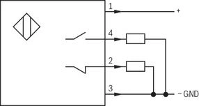 | PNP transistor outputs, load between switching outputs and GND | |||
| Pinout  | 1 | V | 24 | |
| 2, 4 | Switching output | mA | 400 | |
| 3 | Earthing (GND) | V | 0 | |
(For applications outside these values, please consult us!)
Diagrams/characteristic curves
(measured with HLP46, ϑOil = 40 ±5 °C)
Δp-qV characteristic curves
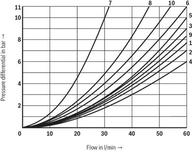
| 7 | Symbol “R” in spool position "b" (A → B) |
| 8 | Symbols “G” and “T” in central position (P → T) |
| Symbols | Direction of flow | |||
| P-A | P-B | A-T | B-T | |
| A | 3 | 3 | – | – |
| B | 3 | 3 | – | – |
| C | 1 | 1 | 3 | 1 |
| D | 5 | 5 | 3 | 3 |
| E | 3 | 3 | 1 | 1 |
| F | 1 | 3 | 1 | 1 |
| G | 6 | 6 | 9 | 9 |
| H | 2 | 4 | 2 | 2 |
| J | 1 | 1 | 2 | 1 |
| L | 3 | 3 | 4 | 9 |
| M | 2 | 4 | 3 | 3 |
| P | 3 | 1 | 1 | 1 |
| Q | 1 | 1 | 2 | 1 |
| R | 5 | 5 | 4 | – |
| T | 10 | 10 | 9 | 9 |
| U | 3 | 3 | 9 | 4 |
| V | 1 | 2 | 1 | 1 |
| W | 1 | 1 | 2 | 2 |
| Y | 5 | 5 | 3 | 3 |
Performance limits
(measured with HLP46, ϑOil = 40 ±5 °C)
Notice!
The specified switching power limits are valid for use with two directions of flow (e. g. from P to A and simultaneous return flow from B to T).
Due to the flow forces acting within the valves, the admissible switching power limit may be considerably lower with only one direction of flow
(e. g. from P to A while port B is blocked)!
In such use cases, please consult us!
Version "WMM" - spring return
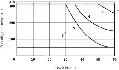
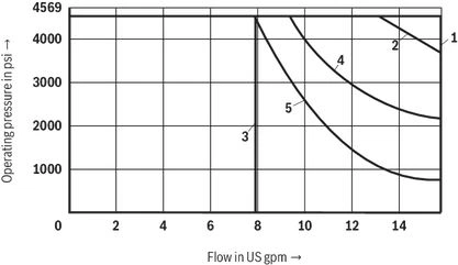
| Characteristic curve | Symbol |
| 1 | E,E1–,M,J,L,Q,U,W, C,D,Y,G,H,R |
| 2 | A,B |
| 3 | V
|
| 4 | F,P |
| 5 | T |
Version "WMM" - with detent
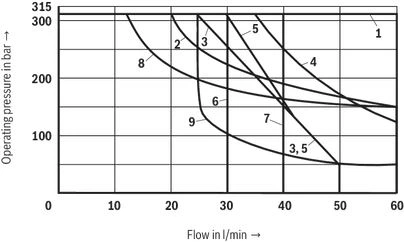
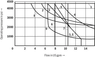
| Characteristic curve | Symbol |
| 1 | E1–,M,H,C,D,Y |
| 2 | E,J,Q,L,U,W |
| 3 | A,B |
| 4 | G,T |
| 5 | F |
| 6 | V |
| 7 | P |
| 8 | R |
| 9 | T |
Symbols/Circuit diagrams
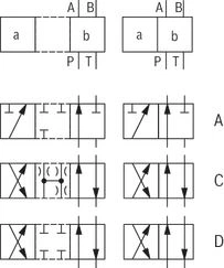
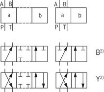
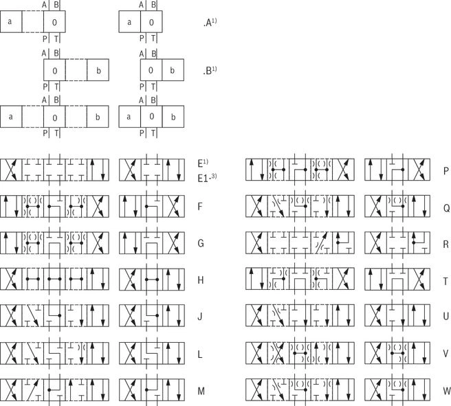
| 1) Example: Symbol E with spool position "a" → ordering code ..EA.. Symbol E with spool position “b" → ordering code ..EB.. | |
| 3) Symbol E1-: P → A/B pre-opening Caution in conjunction with differential cylinders due to pressure intensification! |
Notices!
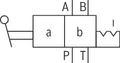
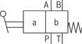
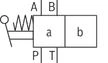
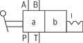
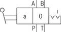
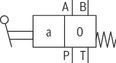
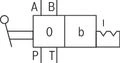
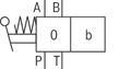
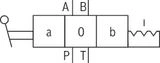
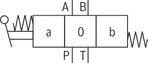
Representation according to DIN ISO 1219-1.
Hydraulic interim positions are shown by dashes.
| Type of actuation |
| Hand lever “WMM” |
 |
 |
 |
 |
 |
 |
 |
 |
 |
 |
Dimensions
load errorDownloads

Отзывы о товаре
Аналогичные товары
Официальный поставщик Bosch Rexroth
Продажи на территории России
Оптовые и розничные продажи
Снижение логистических расходов
Индивидуальные условия
Выгода без посредников
Единая система поставок
Весь ассортимент на складе