Артикул: RX7303
В наличии
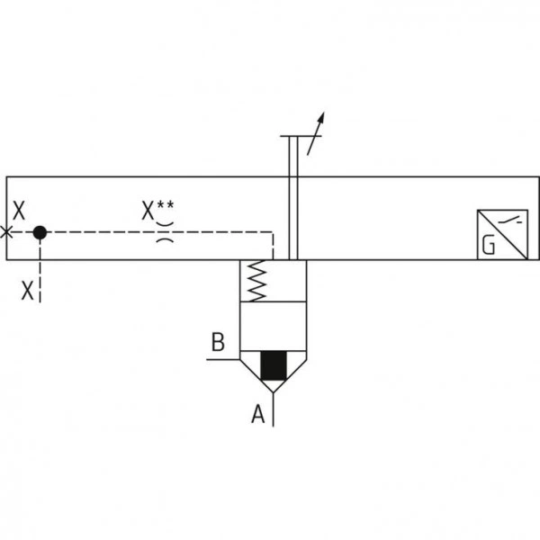
2-way cartridge valves with spool position monitoring LFA..EH2 (control cover)
Цена по запросу Стоимость зависит от выбранного способа оплаты и количества товара.
Не отвечаем 5 минут — скидка на весь заказ!
Нужна скидка? Звони — сделаем лучшее предложение
Работаем по всей России
Возможны самовывоз и доставка по всей территории России
Надежность
Профессиональная поддержка
Description
- Size 16 … 160
- Component series 6X, 2X, 7X
- Maximum operating pressure 420 bar
- Maximum flow 25000 l/min
- Size 16 … 160
- Component series 6X, 2X, 7X
Features
- Functional product design
- Modular set-up:• Cartridge valve with various options• Control cover in various variants for realization of selected functions• Electric monitoring of the spool position
- Power and flow-optimized design:• High flows• Low pressure drops• High switching velocities• Low leakage oil flows
- Robust design:• High reliability• Long life cycle
- Other features:• Small installation size, low weight• Easy to service
Product description
load errorType code
| 01 | 02 | 03 | 04 | 05 | 06 | 07 | 08 | 09 | 10 | 11 | 12 | ||
| LFA | EH2 | – | / | D | Q..24 | F |
| Type | |||
| 01 | Control cover LFA | LFA | |
| Size | |||
| 02 | NG 16 | 16 | |
| NG 25 | 25 | ||
| NG 32 | 32 | ||
| NG 40 | 40 | ||
| NG 50 | 50 | ||
| NG 63 | 63 | ||
| NG 80 | 80 | ||
| NG 100 | 100 | ||
| NG 125 | 125 | ||
| NG 160 | 160 | ||
| Version | |||
| 03 | Control cover version "EH2" | With electrical control of the closed position and stroke limitation incl. installation kit | EH2 |
| Component series | |||
| 04 | Component series 70 ... 79 (70 ... 79: unchanged installation and connection dimensions) 1) | 7X | |
| Component series 60 … 69 (60 … 69: unchanged installation and connection dimensions) 2) | 6X | ||
| Component series 20 … 29 (20 … 29: unchanged installation and connection dimensions) 3) | 2X | ||
| Spool design | |||
| 05 | A1 : A2 = 2 : 1 (annulus area = 50 %; standard version) | CA | |
| A1 : A2 = 14.3 : 1 (annulus area = 7 %) | CB | ||
| Cracking pressure | |||
| 06 | Cracking pressure 1.0 bar | 10 | |
| Cracking pressure 2.0 bar | 20 | ||
| Cracking pressure 4.0 bar | 40 | ||
| Damping | |||
| 07 | Valve poppet with damping nose | D | |
| Spool position monitoring | |||
| 08 | Electrical (NG 16…32) | QMG24 | |
| Electrical (NG 40...160) | Q6G24 | ||
| Remote control port | |||
| 09 | With remote control port | F | |
| Nozzle fitting | |||
| 10 | Orifice in channel X 4) | X... | |
| Seal material | |||
| 11 | NBR seals | no code | |
| FKM seals | V | ||
| Ports, plug screws and orifices | |||
| 12 | Metric | no code | |
| UNC | /12 | ||
| 1) Component series 7X for sizes 16…63. | |
| 2) Component series 6X for sizes 80 and 100. | |
| 3) Component series 2X for sizes 125 and 160. | |
| 4) This orifice is designed as screw-type orifice. If an orifice is to be installed, the respective code letter with the orifice Ø in 1/10 mm has to be entered in the type designation. | |
| Example: X12 = Orifice with Ø1.2 mm in channel X. |
| Version | |
| „CA“ | „CB“ |
 |  |
| Orifice symbol | Symbol in ordering code | |||
| A** |  | A** | This orifice is designed as screw-type orifice. If an orifice is to be installed, the respective code letter with the orifice Ø in 1/10 mm has to be entered in the type designation. Example: A12 = Orifice with Ø1.2 mm in channel A. | |
| Ø1,2 |  | This orifice is designed as bore. No specifications are made in the type designation. (Orifice Ø in mm) | ||
| Z12 |  | This orifice is designed as screw-type orifice. This is a standard orifice. No specifications are made in the type designation. (Orifice Ø in 1/10 mm) | ||
Technical data
general
| Size | 16 | 25 | 32 | 40 | 50 | 63 | 80 | 100 | 125 | 160 | ||
| Ambient temperature range | NBR seals | °C | -30 … +60 | |||||||||
| FKM seals | °C | -20 … +60 | ||||||||||
| MTTFD values according to EN ISO 13849 1) | Years | 150 | ||||||||||
| 1) | For further details, see data sheet 08012 |
hydraulic
| Size | 16 | 25 | 32 | 40 | 50 | 63 | 80 | 100 | 125 | 160 | ||
| Maximum operating pressure | Without directional valve | bar | 400 | 420 | ||||||||
| Anschluss A 1) | bar | 315 350 | ||||||||||
| Port B 1) | bar | 315 350 | ||||||||||
| Port X 1) | bar | 315 350 | ||||||||||
| With electrically monitored spool position | bar | 400 | 420 | |||||||||
| Maximum flow 2) | l/min | 25000 | ||||||||||
| Hydraulic fluid | see table | |||||||||||
| Hydraulic fluid temperature range | NBR seals | °C | -30 … +80 | |||||||||
| FKM seals | °C | -20 … +80 | ||||||||||
| Viscosity range | mm²/s | 2.8 … 500 | ||||||||||
| Maximum admissible degree of contamination of the hydraulic fluid 3) | Class 20/18/15 according to ISO 4406 (c) | |||||||||||
| 1) | dependent on the attached directional valve |
| 2) | NG-dependent; see characteristic curves |
| 3) | The cleanliness classes specified for the components must be adhered to in hydraulic systems. Effective filtration prevents faults and simultaneously increases the life cycle of the components. For the selection of the filters, see www.boschrexroth.com/filter. |
| Hydraulic fluid | Classification | Suitable sealing materials | Standards | |
| Mineral oils | HL, HLP, HLPD, HVLP, HVLPD | NBR, FKM | DIN 51524 | |
| Bio-degradable | Insoluble in water | HETG | NBR, FKM | ISO 15380 |
| HEES | FKM | |||
| Soluble in water | HEPG | FKM | ISO 15380 | |
| Containing water | Water-free | HFDU, HFDR | FKM | ISO 12922 |
| Containing water | HFC (Fuchs Hydrotherm 46M, Petrofer Ultra Safe 620) | NBR | ISO 12922 | |
| Important information on hydraulic fluids!
Flame-resistant – containing water:
| ||||
| Size of the annulus area | |||||||||||
| Surface in cm2 | Version | Size | |||||||||
| 16 | 25 | 32 | 40 | 50 | 63 | 80 | 100 | 125 | 160 | ||
| A1 | „CA“ | 1,89 | 4,26 | 6,79 | 11,1 | 19,63 | 30,2 | 37,9 | 63,6 | 95 | 160,6 |
| „CB“ | 2,66 | 5,73 | 9,51 | 15,55 | 26,42 | 41,28 | 52,8 | 89,1 | 133,7 | 224,8 | |
| A2 | „CA“ | 0,95 | 1,89 | 3,39 | 5,52 | 8,64 | 14,0 | 18,84 | 31,4 | 48 | 79,9 |
| „CB“ | 0,18 | 0,43 | 0,67 | 1,07 | 1,85 | 2,90 | 3,94 | 5,9 | 9,3 | 15,7 | |
| Spool form (damping nose) | |||||||||||
| Size | |||||||||||
| 16 | 25 | 32 | 40 | 50 | 63 | 80 | 100 | 125 | 160 | ||
| Stroke | cm | 0,9 | 1,17 | 1,4 | 1,9 | 2,3 | 2,8 | 3,0 | 3,8 | 4,8 | 6,5 |
| Pilot volume | cm3 | 2,56 | 7,21 | 14,3 | 31,6 | 65,0 | 124 | 170 | 361 | 687 | 1563 |
| Theoretical pilot flow 1) | l/min | 15,4 | 43,3 | 86 | 190 | 390 | 744 | 1020 | 2166 | 4122 | 9378 |
| Cracking pressure in bar | |||||||||||
| Version | Size | ||||||||||
| 16 | 25 | 32 | 40 | 50 | 63 | 80 | 100 | 125 | 160 | ||
| Direction of flow A to B | „CA10“ | 0,70 | 0,68 | 0,72 | 0,71 | 0,67 | 0,64 | 0,88 | 0,88 | 0,88 | ‒ |
| „CA20“ | 2,03 | 2,18 | 2,12 | 2,02 | 2,01 | 2,0 | 1,75 | 1,75 | 1,76 | 1,94 | |
| „CA40“ | 3,50 | 3,90 | 3,80 | 4,0 | 4,11 | 3,8 | 3,13 | 3,04 | ‒ | ‒ | |
| „CB10“ | 0,49 | 0,50 | 0,51 | 0,51 | 0,48 | 0,47 | 0,63 | 0,63 | 0,62 | ‒ | |
| „CB20“ | 1,44 | 1,62 | 1,52 | 1,44 | 1,5 | 1,5 | 1,26 | 1,25 | 1,25 | 1,4 | |
| „CB40“ | 2,48 | 2,90 | 2,70 | 2,86 | 3,05 | 2,8 | 2,25 | 2,17 | ‒ | ‒ | |
| Direction of flow B to A | „CA10“ | 1,38 | 1,53 | 1,42 | 1,43 | 1,47 | 1,37 | 1,77 | 1,78 | 1,73 | ‒ |
| „CA20“ | 4,05 | 4,91 | 4,25 | 4,06 | 4,57 | 4,33 | 3,53 | 3,54 | 3,50 | 3,9 | |
| „CA40“ | 6,96 | 8,74 | 7,6 | 8,05 | 9,34 | 8,15 | 6,3 | 6,2 | ‒ | ‒ | |
| „CB10“ | 7,43 | 6,69 | 7,24 | 7,37 | 6,88 | 6,62 | 8,4 | 9,4 | 8,9 | ‒ | |
| „CB20“ | 21,3 | 21,5 | 21,6 | 20,9 | 21,4 | 20,9 | 16,9 | 18,7 | 17,9 | 20 | |
| „CB40“ | 36,6 | 38,3 | 38,6 | 41,5 | 43,6 | 39,4 | 30,2 | 32,5 | ‒ | ‒ | |
| 1) Switching time = 10 ms |
(For applications outside these values, please consult us!)
Diagrams/characteristic curves
(simulated with HLP46, ϑoil = 40±5 °C)
Size 16 (A → B)

Size 16 (B → A)
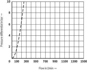
Size 25 (A → B)

Size 25 (B → A)

Size 32 (A → B)

Size 32 (B → A)

Size 40 (A → B)

Size 40 (B → A)

Size 50 (A → B)

Size 50 (B → A)

Size 63 (A → B)

Size 63 (B → A)

Size 80 (A → B)
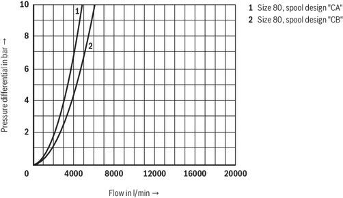
Size 80 (B → A)

Size 100 (A → B)

Size 100 (B → A)
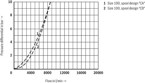
Size 125 (A → B)

Size 125 (B → A)
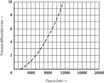
Size 160 (A → B)
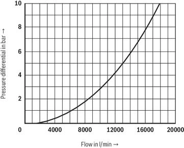
Size 160 (B → A)
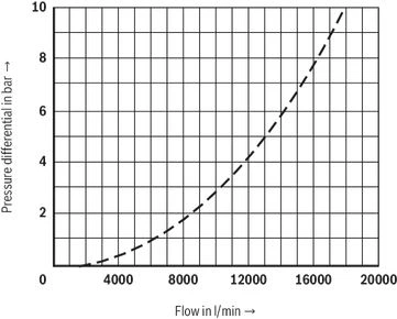
Notice:
The indicated characteristic curves have been determined without inserted springs.
| Orifices | |
| Thread | Orifice Ø in mm |
| M6 conical | 0,5 … 3,0 |
| M8 x 1 conical | 0,5 … 4,0 |
| G3/8 | 0,8 … 6,0 |
| G1/2 | 1,0 … 8,0 |
Other orifices upon request.
| Plug screws | |
| Thread | Tightening torqueMA in Nm |
| M6 | – |
| M8 x 1 | 7 |
| G3/8 | 55 |
| G1/2 | 80 |
| G3/4 | 135 |
| G1 | 225 |
| G1 1/4 | 360 |
Symbols/Circuit diagrams
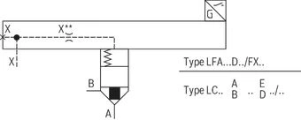
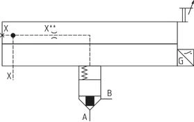
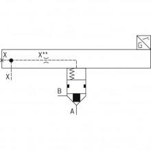
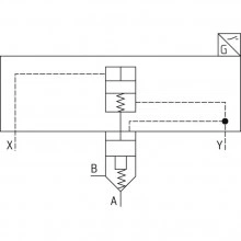
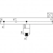
LFA . EH2… (NG16 … 32)
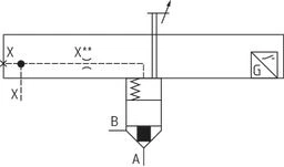
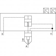
LFA . EH2… (NG40 … 160)
Electrical connection
load errorComponents
load errorDimensions
load errorInformation
load errorDownloads
 | 2-way cartridge valves with spool position monitoring, passively controlled Data Sheet | RE21015 | 2019-07-01 | English | PDF | 2.3MB Product Groups: Logic elements - directional function |
Отзывы о товаре
Аналогичные товары
Официальный поставщик Bosch Rexroth
Продажи на территории России
Оптовые и розничные продажи
Снижение логистических расходов
Индивидуальные условия
Выгода без посредников
Единая система поставок
Весь ассортимент на складе