
Доступно к заказу
Цена по запросу
И выбери подходящего.
Description
Features
- High power density
- High torque density
- Energy efficient
- Flexible, many sizes, few mechanical interfaces
- Insensitive for shock loads
- Very low moment of inertia
- Small footprint (total occupied volume)
- Freewheeling possibility
- Through hole diameter 270 mm
- Tandem mounting possibilty
- High starting torque
- 4-quadrant operation
- Dynamic brake
- Constant torque throughout speed range
- Frequent start/stop capacity
Product description
When it comes to production, everyone wants more. But these days there’s less of everything else: from available time to the energy and resources for the job. With the Hägglunds CBm direct drive from Bosch Rexroth, the equation is easier to solve. The Hägglunds CBm packs 50 % more torque into a motor that’s smaller and 50 % lighter than its predecessor. That gives it the world’s highest torque-to-weight ratio. Even so, it has all the advantages you’d expect from a direct drive. Full torque from zero, protection from shock loads and fourquadrant operation are part of the same small package. Put simply, the Hägglunds CBm does more with less – and lets you do the same. From industry to offshore, you can handle more work with less space, less energy and less weight on the driven shaft. That means greater productivity with a smaller footprint. And that’s an ingenious solution.
Bosch Rexroth hydraulics technology is counted on worldwide to deliver outstanding performance in industrial and mobile applications. As the technology leader, we refine each system to incorporate the quality and capabilities you need to help maximize your system performance.
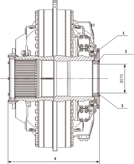
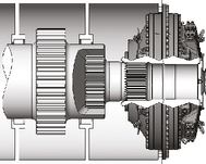
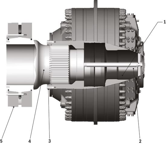
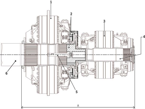
Section view of radial piston hydraulic motor
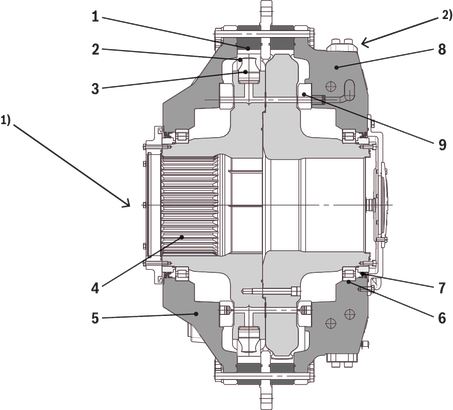
| 1) | Shaft side |
| 2) | Connection side |
| 1 | Cam ring |
| 2 | Cam roller |
| 3 | Piston |
| 4 | Cylinder block, spline |
| 5 | Housing cover |
| 6 | Cylindrical roller bearing |
| 7 | Wear ring |
| 8 | Connection housing |
| 9 | Distributor |
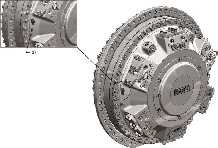
Bosch Rexroth‘s hydraulic industrial motor Hägglunds CBm is of the radial piston type with a rotating cylinder block/hollow shaft and a stationary housing. The cylinder block is mounted in fixed roller bearings in the housing. An even number of pistons are radially located in bores inside the cylinder block, and the distributor directs the incoming and outgoing oil to and from the working pistons. Each piston is working against a cam roller.
When the hydraulic pressure is acting on the pistons, the cam rollers are pushed against the slope on the cam ring that is rigidly connected to the housing, thereby producing a torque. The cam rollers transfer the reaction force to the pistons which are guided in the cylinder block. Rotation therefore occurs, and the torque available is proportional to the pressure in the system.
Oil main lines are connected to ports A1 and C1 in the connection block and drain lines to one of the D-ports in the motor housing.
The motor is connected to the shaft of the driven machine through the hollow shaft of the cylinder block. The torque is transmitted by splines.
Features as an option for Hägglunds CBm:
Read for information:
Chapter "Techncial data" – section "Through hole kit"
Features included as standard in Hägglunds CBm:
Read for information:
Chapter "Technical data" – section "Magnetic plug"
Chapter "Technical data" – section "Temperature sensor"
Quality
To assure our quality we maintain a Quality Assurance System, certified to standard ISO 9001.
Fluid connections
Hydraulic symbol

Port locations and dimensions, see table "Port dimensions".
Port connections
Connection side of the motor
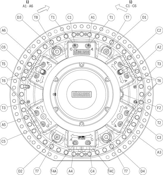
| 1) | Rotation flow inlet |
Shaft side of the motor
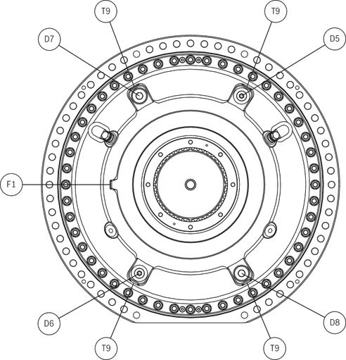
Port dimensions
| Connection | Description | Dimensions | Remarks |
| C1 | Main connection | 2“ 1) | If C is used as the inlet, the motor shaft rotates clockwise, viewed from the motor shaft side. |
| C2, C3, C4, C5, C6 | Alternative main connection | Normally plugged at delivery. | |
| A1 | Main connection | If A is used as the inlet, the motor shaft rotates counterclockwise, viewed from the motor shaft side. | |
| A2, A3, A4, A5, A6 | Alternative main connection | Normally plugged at delivery. | |
| D3 | Drain outlet | G 2“ | |
| D1, D2, D5, D6 | Alternative drain outlets / or flushing inlet | G 1 1/4“ | |
| D4, D7, D8 | Alternative drain outlets / or flushing inlet | G 2“ | |
| F1, F2 | Flushing connections | G 1/4“ | For flushing of radial lip seal. Normally plugged. |
| T1 | Test connection | M16 x 2 | Used to measure pressure and/or temperature at the main connections. |
| T2 | Test connection | Used to measure case pressure and/or temperature in case drain oil. | |
| T3 | Test connection | G 1/4“ | Normally plugged at delivery. |
| T4A, T4C | Pressure connection | G 1/2“ | Connection for double ended torque arm. |
| T5 | Temperatur sensor PT100 | G 1/4“ | Used to measure temperature in the housing. |
| T6 | Alternative test connection or pressure connection | Normally plugged at delivery. | |
| T8 | Magnetic plug | 1 1/16-12-UN-2B | Used to monitor impurities in the oil. |
| T7, T9 | Alternative magnetic plug connection | Normally plugged at delivery. |
| 1) | SAE flange J 518, code 62, 420 bar. |
Type code
In order to identify Hägglunds equipment exactly, the following ordering code is used. These ordering codes should be stated in full in all correspondence e.g. when ordering spare parts.
| 01 | 02 | 03 | 04 | 05 | 06 | 07 | 08 | 09 | 10 | 11* | 12* |
| CB | M | S | 0 |
| Motor Series | |||||||
| 01 | Compact | CB | |||||
| Type | |||||||
| 02 | Magnum | M | |||||
| Frame size | |||||||
| 03 | CBM 2000 | 2000 | |||||
| CBM 3000 | 3000 | ||||||
| CBM 4000 | 4000 | ||||||
| CBM 5000 | 5000 | ||||||
| CBM 6000 | 6000 | ||||||
| Nominal size (specific torque in Nm/bar) (see chapter "Technical data" – Table "Motor data ‒ specific") | |||||||
| 04 | Frame size 2000 | 1000 (1,000) | 1200 (1,200) | 1400 (1,400) | 1600 (1,600) | 1800 (1,800) | 2000 (2,000) |
| ● | ● | ● | ● | ● | ● | ||
| Frame size 3000 | 2200 (2,200) | 2400 (2,400) | 2600 (2,600) | 2800 (2,800) | 3000 (3,000) | ||
| ● | ● | ● | ● | ● | |||
| Frame size 4000 | 3200 (3,200) | 3400 (3,400) | 3600 (3,600) | 3800 (3,800) | 4000 (4,000) | ||
| ● | ● | ● | ● | ● | |||
| Frame size 5000 | 4600 (4,600) | 5000 (5,000) | |||||
| ● | ● | ||||||
| Frame size 6000 | 5600 (5,600) | 6000 (6,000) | |||||
| ● | ● | ||||||
| Mounting alternatives, shaft | |||||||
| 05 | Splines DIN 5480 N | S | |||||
| Prepared for brake or tandem kit (see chapter "Accessories" – section "Hägglunds tandem motors") | |||||||
| 06 | Motor not prepared for TA kit | ● | A | ||||
| Motor prepared for TA kit | ● | B | |||||
| Displacement shift valve | |||||||
| 07 | Motor not prepared for displacement shift | 0 | |||||
| Type of seal (see chapter "Technical Data" – section "Type of seal") | |||||||
| 08 | NBR (Nitrile) | ● | N | ||||
| FPM (Viton) | ● | V | |||||
| Through hole kit (see chapter "Technical data" – section "Through hole kit") | |||||||
| 09 | No | ● | 0 | ||||
| Yes | ● | H | |||||
| Increased robustness (see chapter "Technical Data" – section "Increased robustness") | |||||||
| 10 | No | ● | A | ||||
| Yes | ● | C | |||||
| Modification *) | |||||||
| 11 | 00 ... 99 | ||||||
| Design | |||||||
| 12 | Standard | 00 | |||||
| Special index *) | 01 ... 99 | ||||||
| ● = Available | |
| – = Not available | |
| *) | To be filled in by Bosch Rexroth DC-IA/EHD |
Technical data
Calculation fundamentals
| Output power |  | kW (on driven shaft) |
| Output torque (ηm = 98 %) |  | Nm |
| Pressure required (ηm = 98 %) | 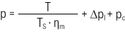 | bar |
| Flow rate required |  | l/min |
| Output speed | 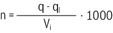 | rpm |
| Inlet power |  | kW |
| Quantity | Symbol | Unit |
| Power | P | kW |
| Output torque | T | Nm |
| Specific torque | Ts | Nm/bar |
| Rotational speed | n | rpm |
| Required pressure | p | bar |
| Pressure loss | Δpl | bar |
| Charge pressure | pc | bar |
| Flow rate required | q | l/min |
| Total volumetric loss | ql | l/min |
| Displacement | Vi | cm3/rev |
| Mechanical efficiency | ηm | 0.981) |
| 1) | Not valid for starting efficiency |
Recommended charge pressure
The hydraulic system must be such that the motor will recieve sufficient charge pressure at the low pressure port. This applies to all types of installations.
The motor working in driving mode only
For CBm 2000 - CBm 6000. The pressure at the low pressure port, should, during operation of the motor, be at least 1 bar above the case pressure independent of numbers of ports that are connected. Two cases to be considered:
Case 1: No shock loads.
Required charge pressure = case pressure + 1 bar during operation, but shall not be below 2 bar
Case 2: With shock loads.
Required charge pressure at the outlet port corresponds to 30 % of value given in diagram. See Figure "Recommended charge pressure for motor working in braking mode, Hägglunds CBm 4-port connection. Valid for oil viscosity 40 mm2/s" and Figure "Recommended charge pressure for motor working in braking mode, Hägglunds CBm 8-port connection. Valid for oil viscosity 40 mm2/s"
The motor working in braking mode
Required charge pressure at the inlet port is according to diagram. See Figure "Recommended charge pressure for motor working in braking mode, Hägglunds CBm 4-port connection. Valid for oil viscosity 40 mm2/s" and Figure "Recommended charge pressure for motor working in braking mode, Hägglunds CBm 8-port connection. Valid for oil viscosity 40 mm2/s".
Notice!
The diagrams is valid for 1 bar case pressure.
With increasing case pressure the charge pressure must be increased accordingly.
Recommended charge pressure for motor working in braking mode, Hägglunds CBm 4-port connection. Valid for oil viscosity 40 mm2/s.
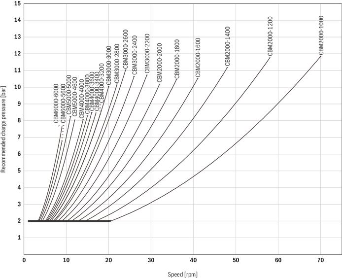
Recommended charge pressure for motor working in braking mode, Hägglunds CBm 8-port connection. Valid for oil viscosity 40 mm2/s.
Hydraulic fluids
The hydraulic motor Hägglunds CBm is primarily designed for operation with hydraulic fluids according to ISO 11158 HM.
Before the start of project planning, see data sheet RE 15414, Hydraulic fluid quick reference, for detailed information on hydraulic fluids and specific additional demands.
Applicable fluids
| ISO 11158 (DIN 51524-2) | ISO 11158 (DIN 51524-3) | ISO 15380 | ISO 12922 |
| HM (HLP) | HV (HVLP) | HEES | HFB |
| HEPG | HFC | ||
| HEPR | HFDR | ||
| HFDU |
Filtration of the hydraulic fluid
A contamination level better than 18/16/13 according to ISO 4406 is required.
The less contamined the fluid, the longer the service life of the hydraulic motor.
Details regarding the selection of hydraulic fluid
The hydraulic fluid should be selected such that the operating viscosity in the temperature range, as measured in the motor housing, is within optimum operation range, see Figure "Selection diagram for viscosity ranges with straight fluids, i.e. viscosity index 100." General recommendation is to have a system temperature of 50 °C, see dotted line in figure below. An ISO VG 68 fluid will render just above 40 mm2/s at this point.
- Optimum viscosity range is 40 to 150 mm2/s.
- Running above 150 mm2/s or below 40 mm2/s results in reduced efficiency.
- Running above 400 mm2/s results in substantial efficiency loss.
- Starting at above 10000 mm2/s imparts unnecessary strain on parts.
- Running below 30 mm2/s may impact service life.
- Running below 20 mm2/s may render instant seizure.
The operating temperature is also limited by the seal type, see Table "General data".
Selection diagram for viscosity ranges with straight fluids, i.e. viscosity index 100
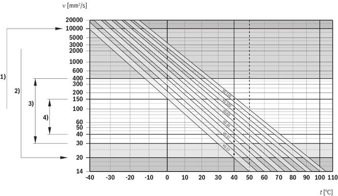
| 1) | Maximum viscosity at cold start |
| 2) | Minimum viscosity for short-term operation |
| 3) | Continuous operation |
| 4) | Optimal operation |
| v | Viscosity |
| t | Temperature |
Fire resistant fluid
Operating with fire resistant fluids (ISO 12922)
Operating with fire resistant fluids
| Fluid | Approved | Seals | Internal paint |
| HFA: Oil (3 ... 5%) in water emulsion | No | - | - |
| HFB: Inverted emulsion 40 ... 45% water in oil | Yes | Nitrile (std motor) | Not painted 1) |
| HFC: Water-glycol | |||
| HFD synthetic fluids | |||
| HFD:R - Phosphate esters | Yes | Viton | Not painted 1) |
| HFD:S - Chlorinated hydrocarbons | |||
| HFD:T - Mixture of the above | |||
| HFD:U - Other compositions | |||
| 1) | Must be specified in the order. |
Down rating of pressure data and basic rating life
There are fluids with lesser lubricity, or characteristics incompatible with the system components, that needs specific precautions.
For these fluids, maximum pressure and rated life must be down-rated. See Table "Down-rating factors" for fluids that are subject to down-rating.
Down-rating factors
| Fluid group | Down-rating | |
| Pressure 1) | Rated life 2) | |
| HFB (>40% water in fluid) | 0.7 x stated | 0.26 x LHM |
| HFC (>35% water in “glycol”) | ||
| HFDR (phosphate esters) | 0.9 x stated | 0.8 x LHM |
| HFDU (other water free) | ||
| 1) | Pressure as stated on the motor number plate. |
| 2) | LHM is the rated life expectancy with a straight mineral oil, fluid group HM. |
Notice!
Bosch Rexroth or its authorised representative must always be contacted for approval in the case of these types of fluids.
Environmentally acceptable fluids (ISO 15380)
| Fluid | Approved | Seals | Internal paint |
| Vegetable 1)/2) Fluid | Yes | Nitrile (std motor) | - |
| Synthetic 2)/3) |
| 1) | Vegetable fluids give good lubrication and small change of viscosity with different temperature. Vegetable fluids must be controlled every 3 months and temperature shall be less than +45 °C to give good service life for the fluid. |
| 2) | Environmental acceptable fluids give the same service life for the drive, as mineral oil. |
| 3) | The fluid shall have max. 10 g/100 g according to ISO 3961: 2009 / DIN 52341 |
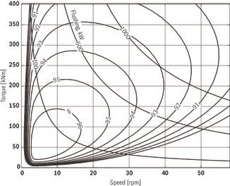
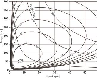
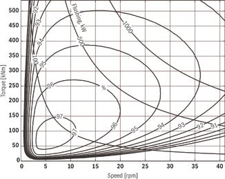
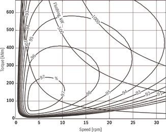
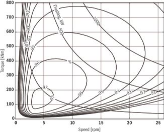
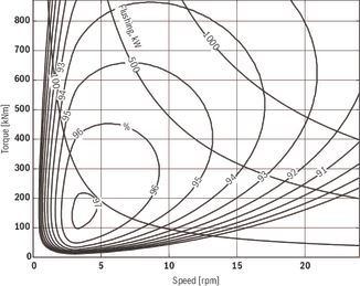
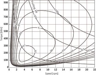
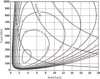
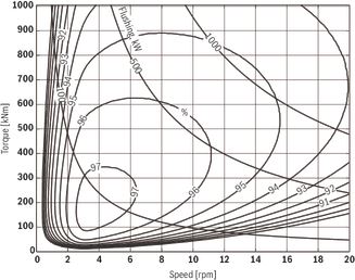
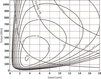
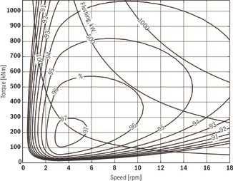
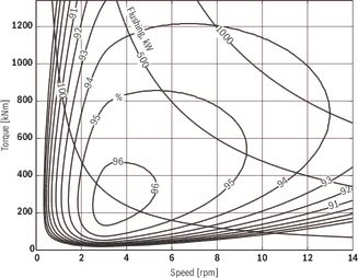
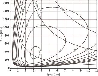
Overall efficiency
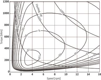
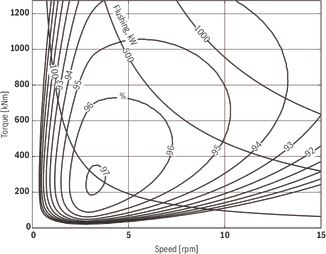
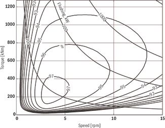
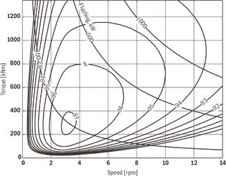
The diagrams are valid for oil viscosity 40 mm2/s and low pressure 15 bar at the motor main ports A or C.
Number of port connections recomended:
- 2-port for oil flow up to 750 l/min
- 4-port for oil flow up to 1500 l/min
- 6-port for oil flow up to 2250 l/min
- 8-port for oil flow up to 3000 l/min
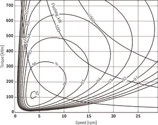
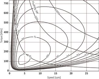
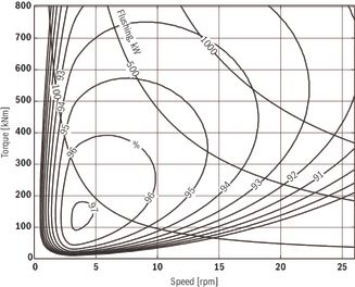
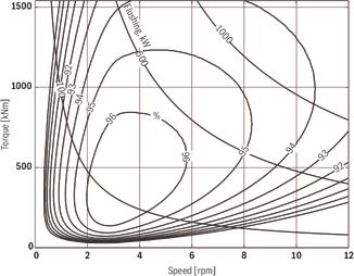
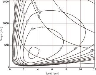
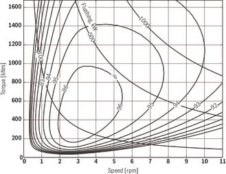
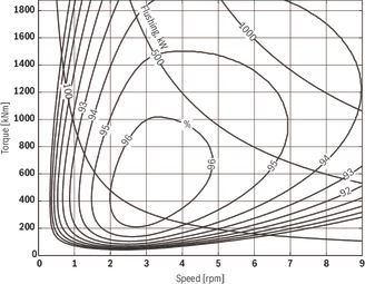
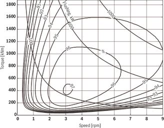
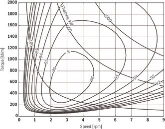
Overall efficiency - CBm 2000
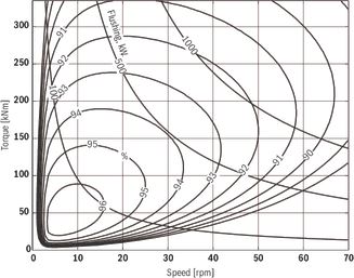 | 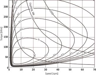 |
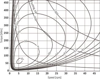
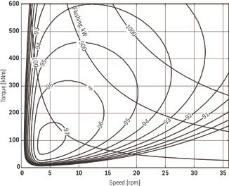
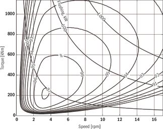
| Hägglunds CBm 2000-1000, 4 port connection | Hägglunds CBm 2000-1000, 8 port connection |
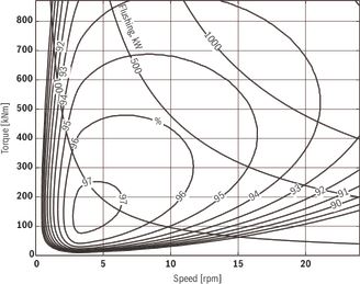
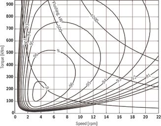
 |  |
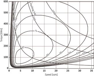
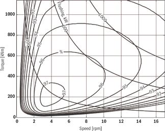
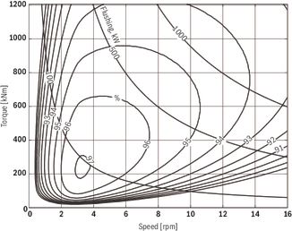
| Hägglunds CBm 2000-1200, 4 port connection | Hägglunds CBm 2000-1200, 8 port connection |
 | 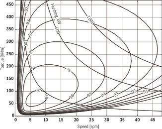 |
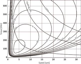
| Hägglunds CBm 2000-1400, 4 port connection | Hägglunds CBm 2000-1400, 8 port connection |
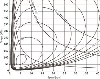 |  |
| Hägglunds CBm 2000-1600, 4 port connection | Hägglunds CBm 2000-1600, 8 port connection |
 |  |
| Hägglunds CBm 2000-1800, 4 port connection | Hägglunds CBm 2000-1800, 8 port connection |
 |  |
| Hägglunds CBm 2000-2000, 4 port connection | Hägglunds CBm 2000-2000, 8 port connection |
Overall efficiency - CBm 3000
 |  |
| Hägglunds CBm 3000-2200, 4 port connection | Hägglunds CBm 3000-2200, 8 port connection |
 |  |
| Hägglunds CBm 3000-2400, 4 port connection | Hägglunds CBm 3000-2400, 8 port connection |
 |  |
| Hägglunds CBm 3000-2600, 4 port connection | Hägglunds CBm 3000-2600, 8 port connection |
 |  |
| Hägglunds CBm 3000-2800, 4 port connection | Hägglunds CBm 3000-2800, 8 port connection |
 |  |
| Hägglunds CBm 3000-3000, 4 port connection | Hägglunds CBm 3000-3000, 8 port connection |
Overall efficiency - CBm 4000
 |  |
| Hägglunds CBm 4000-3200, 4 port connection | Hägglunds CBm 4000-3200, 8 port connection |
 |  |
| Hägglunds CBm 4000-3400, 4 port connection | Hägglunds CBm 4000-3400, 8 port connection |
 |  |
| Hägglunds CBm 4000-3600, 4 port connection | Hägglunds CBm 4000-3600, 8 port connection |
 |  |
| Hägglunds CBm 4000-3800, 4 port connection | Hägglunds CBm 4000-3800, 8 port connection |
 |  |
| Hägglunds CBm 4000-4000, 4 port connection | Hägglunds CBm 4000-4000, 8 port connection |
Overall efficiency - CBm 5000
 |  |
| Hägglunds CBm 5000-4600, 4 port connection | Hägglunds CBm 5000-4600, 8 port connection |
 |  |
| Hägglunds CBm 5000-5000, 4 port connection | Hägglunds CBm 5000-5000, 8 port connection |
Overall efficiency - CBm 6000
 |  |
| Hägglunds CBm 6000-5600, 4 port connection | Hägglunds CBm 6000-5600, 8 port connection |
 |  |
| Hägglunds CBm 6000-6000, 4 port connection | Hägglunds CBm 6000-6000, 8 port connection |
Pressure loss diagrams
Pressure loss, oil viscosity 40 mm2/s

Quick selection diagram
Rated life for Hägglunds CBm is calculated according to DIN ISO 281 Apendix 1.
The diagram below represents the torque and speed, corresponding to a modified rating life L10mh = 40 000 h. Oil viscosity in motor case 40 mm2/s. Contamination level not exceeding ISO 4406:1999 18/16/13 (NAS 1638, class 7). The diagram is based on a charge pressure of 15 bar.
Quick selection diagram

Notice!
Higher case oil viscosity increases the motor rating life considerably.
Reduced temperature in the motor case, increase rating life for the motor.
Draining, venting and flushing of the motor
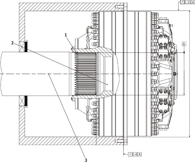
Horizontal mounting

| 1 | Magnetic plug, T8 |
| 2 | Drain line connection |
| 3 | Flushing flow inlet |
| 4 | Alternative flushing flow inlet for flange mounted motors. See chapter "Mounting" - section "Flange mounting with splines". |
Horizontal mounting
When the motor is installed with the shaft in the horizontal plane, the highest of the four drain outlets D1, D2, D3 or D4 must always be used (see Figure "Horizontal mounting"). Drain line must be connected to the tank with a minimum of restrictions, to ensure that the maximum case pressure is not exceeded.
A magnetic plug is pre assembled from factory in connection T8, in the drain outlet D3.
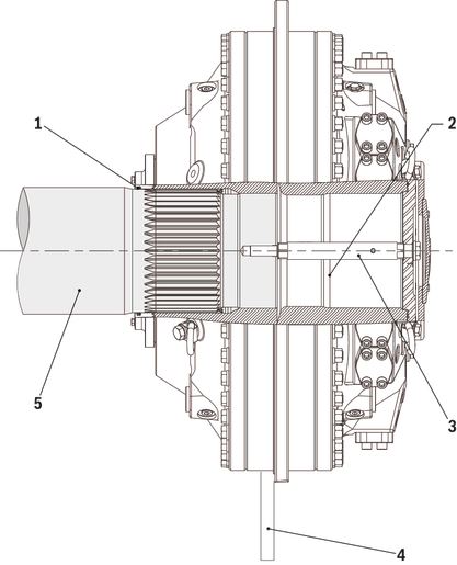
Vertical mounting

| 1 | Orifice Ø1.0 mm |
| 2 | Radial seal |
| 3 | Drain line connection |
| 4 | Low pressure |
| 5 | Flushing flow inlet |
Vertical mounting
When the motor is mounted vertically, one of the highest drain ports D1 to D8 must be used.
Flushing (lubrication) of radial seal from low pressure is necessary.
A) Motor shaft pointing downwards
The drain line must be connected to one of the drain ports D1 to D4 in the connection block. (See Figure "Vertical mounting" alt.: A) Shaft side downwards).
The flushing connection F2 shall be connected to low pressure. With bidirectional drives, use the connection with lowest average pressure.
(Connecting to high pressure will increase the motor drain flow).
B) Motor shaft pointing upwards
The drain line must be connected to one of the drain ports D5 to D8 in the shaft end housing. (See Figure "Vertical mounting", alt.: B) Shaft side upwards). The flushing connection F1 on the shaft end housing should be connected to the low pressure. With bidirectional drives, use the connection with lowest average pressure.
(Connecting to high pressure will increase the motor drain flow).
Flushing
Flushing of motor case
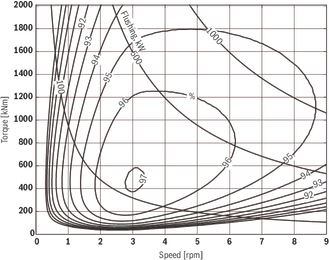
The CBm motors have very high overall efficiency, and they are frequently used in applications with high power.
To avoid high temperature in the case, the losses generated in the motors must be cooled away. High temperature gives lower viscosity and this gives reduction in basic rating life and max allowed power for the motor.
Flushing flow inlets, see Figure "Horizontal mounting" and Figure "Vertical mounting".
For continuous duty the motors must be flushed when power exceed the following max power:
Maximum motor power without flushing
| Frame size | Flushing limit power, EFL |
| CBm 2000-6000 | 500 kW |
When the motor have to be flushed, the required flushing flow can be calculated according to following:
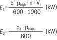
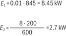
E1 = Power loss due to mechanical losses = c ⋅ motor power
E2 = Power loss due to volumetric losses
| phigh | motor high pressure | [bar] |
| n | motor speed | [rpm] |
| Vi | motor displacement | [cm3/rev] |
| ql | motor leakage | [l/min] |
Heat transmitted to air at ambient temperature +20 °C and motor case temperature +50 °C.
Hägglunds CBm 2000–6000 2.5 kW
c = 0.01 for Hägglunds CBm. Total power loss ET = E1 + E2
Required flushing to keep motor case maximum 10 °C warmer than flushing oil:
q flushing = 3.4 · (E1 + E2 - Heat transmitted to air) l/min.
Viscosity in the motor case must be controlled according to diagram, Figure "Selection diagram for viscosity ranges with straight fluids, i.e. viscosity index 100".
Example:
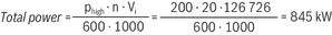
Hägglunds CBm 2000 working at 200 bar and n = 20 rpm.
The motor case must be flushed
q flushing = 3.4 · (E1 + E2 - Heat transmitted to air) = 3.4 · (8.45 + 2.7 - 2.5) = 29 l/min
External leakage
External leakage is from the distributor to the motor case and from the piston assembly to the motor case.
External leakage
Valid for 40 mm²/s
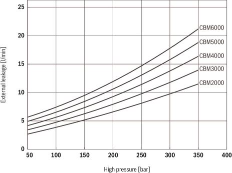
The diagram shows the avarage values.
Actual flow rate = speed ⋅ displacement + external leakage
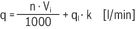
Viscosity factor K
Variation in external leakage at different oil viscosities. When calculating external leakage using other viscosities than 40 mm2/s, multiply the value given in the external leakage diagram by the factor K.
Viscosity factor K
Freewheeling
The function of freewheeling
Hägglunds CBm motors can be operated in freewheeling. Principally this is performed by disengaging the pistons, allowing the rotating group to rotate as a flywheel on its main bearings. The piston units are not engaged and thus there is no oil flow to cause a flow loss, Hägglunds motors of standard design are suitable for this performance due to the following facts:
- Pistons are not actuated by any return springs.
- The motor case can withstand sufficient case pressure to force the pistons toward the bottom of each cylinder bore and keep them in this position.
The basic function of the freewheeling is to have the drain ports D1-D8 lightly pressurized while main ports A and C are without restriction drained directly to the fluid reservoir. See figure "Schematic principle freewheeling". The case pressure introduced in the normal drain connection will then act on the outer surface of each piston assembly pressing them towards the motor centre.
The rotating part of the motor (cylinder block with piston and cam roller) can now rotate on its main bearings without any pumping of oil, as the piston with cam rollers have lost any contact with the cam ring. See Figure "Freewheeling".
During freewheeling periods, the following functions must be performed:
- Main connections A & C of the motor drained to reservoir.
- Fail-safe type brake released, if used.
- An adequate pressure introduced into the drain ports of the motor. See Figure "Power loss freewheeling, oil viscosity 40 mm²/s".
Freewheeling

Notice!
It is not allowed for the pistons to extend back to the camring, until the motor has reached a complete standstill.
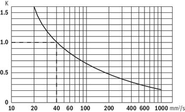
Circuit design
The following schematic explains a system (closed/open) with freewheeling (activated mode illustrated) as a permanent feature for the application.
Schematic principle freewheeling
Freewheeling valve function, see chapter "Accessories" – section "Freewheeling valve VFWCB 600".
Oil volume for freewheeling
Freewheeling conditions are obtained by pressurizing the case via the drain connections and drain the main ports to tank. To retract all pistons completely, a certain oil volume is required depending upon motor type. This oil volume can be calculated from the following:

| VF | Needed Freewheeling volume | [cm3] |
| Vi | Total displacement of the motor | [cm3] |
| NL | Number of lobes for one camring |
In word:
Required freewheeling volume is the displacement of the motor divided by twice the number of cam lobes for one camring.
Number of cam lobes for CBm motors:
CBm 2000 = 18 lobes/camring
CBm 3000 = 18 lobes/camring
CBm 4000 = 18 lobes/camring
CBm 5000 = 18 lobes/camring
CBm 6000 = 18 lobes/camring
Freewheeling can be achieved in several ways depending upon type of application. One way of solving the problem is via an accumulator providing required freewheeling volume when main ports are opened to tank. The size of the accumulator can be calculated when considering that the case pressure should be set at 1.5 ... 2 bar in freewheeling circuits. Thus the required volume should be obtained at a pressure drop in the accumulator from 2 bar down to 1.5 bar.
It should also be mentioned here that freewheeling conditions can be reached via the oil flow from either charge pump or main pump. The accumulator is then not necessary and Freewheeling can be obtained very fast.
A case pressure of 1.5 ... 2 bar must be maintained in the motor case also when motor is not in a freewheeling position. These requirements are normally reached by installing a 1 ... 1.5 bar relief value in the return drain line from the motor.
Power loss freewheeling
Even if the freewheeling operation takes place with lowest possible friction in the main bearings and with no flow losses in the main ports of the motor, a powerloss must take place in the motor case due to viscous friction between moving and fixed parts. This powerloss is expressed in diagram, Figure "Power loss freewheeling, oil viscosity 40 mm²/s".
Case flushing is required to prevent overheating, see Figure "Power loss freewheeling, oil viscosity 40 mm²/s".
Required case pressure 1.5 ... 2 bar.
Case oil temperatur to be below 50 °C.
Power loss freewheeling, oil viscosity 40 mm²/s
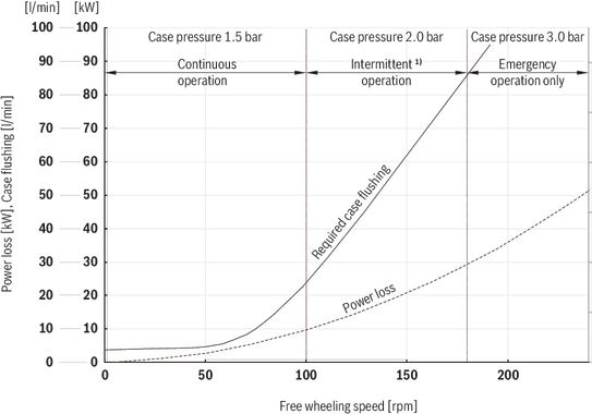
| 1) | Viton seals are recomended for speeds above 100 rpm. |
Notice!
Freewheeling will require exchange of oil in the housing to prevent overheating.
In order to accomplish proper freewheeling, a case pressure of 1.5 bar has to be maintained. On the other hand, a higher casing pressure than 2 bar should be avoided in order to achieve good life of the main radial shaft seal.
Permissible external loads
External load with torque arm mounting
Shaft mounted motor with torque arm
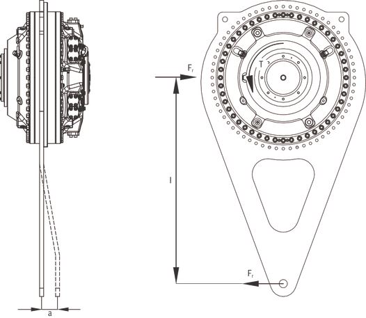
If non standard torque arms TCA are used, forces must be checked for main bearings and coupling.

| Fr | Total radial force on fixed motor mounting |
| T | Output torque for motor |
| l | Lever length |
| a | The axial distance for action point of radial force |
Permissible external dynamic loads
Permissible external dynamic loads Hägglunds CBm 2000
Torque arm mounted motor. Viscosity 40 mm2/s, speed 10 rpm.
Notice!
When flange mounted motor, please contact Bosch Rexroths representative.
Axial loads: Permissible axial load for intermittent duty
Fa = 150 000 N.
Remark: For continuous axial load applications, please contact your Bosch Rexroth representative.
Permissible external dynamic loads Hägglunds CBm 3000
Torque arm mounted motor. Viscosity 40 mm2/s, speed 6 rpm
Notice!
When flange mounted motor, please contact Bosch Rexroths representative.
Axial loads: Permissible axial load for intermittent duty
Fa = 150 000 N.
Remark: For continuous axial load applications, please contact your Bosch Rexroth representative.
Permissible external dynamic loads CBm 4000
Torque arm mounted motor. Viscosity 40 mm2/s, speed 4 rpm.
Notice!
When flange mounted motor, please contact Bosch Rexroths representative.
Axial loads: Permissible axial load for intermittent duty
Fa = 150 000 N.
Remark: For continuous axial load applications, please contact your Bosch Rexroth representative.
Permissible external dynamic loads CBm 5000
Torque arm mounted motor. Viscosity 40 mm2/s, speed 3 rpm.
Notice!
When flange mounted motor, please contact Bosch Rexroths representative.
Axial loads: Permissible axial load for intermittent duty
Fa = 150 000 N.
Remark: For continuous axial load applications, please contact your Bosch Rexroth representative.
Permissible external dynamic loads CBm 6000
Torque arm mounted motor. Viscosity 40 mm2/s, speed 2.5 rpm.
Notice!
When flange mounted motor, please contact Bosch Rexroths representative.
Axial loads: Permissible axial load for intermittent duty
Fa = 150 000 N.
Remark: For continuous axial load applications, please contact your Bosch Rexroth representative.
Permissible external static load
Low speed performance
For Hägglunds CBm 2000 to CBm 6000
Figure "Speed deviation" shows speed deviation factor "i" as function of nav.
A is max. deviation from average speed in r/min.
nav is average speed in r/min.
A = nav · i (rpm)
nmax = nav + A (rpm)
nmin = nav - A (rpm)
The figure refers to 40 mm2/s viscosity, and moment of inertia 600 kgm2.
Speed deviation
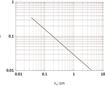
Example:
nav = 1 gives i = 0.028 (see figure) and A = 1 · 0.28 = 0.03 rpm.
Obtained amplitude value shall be reduced to two decimals.
nmax = 1.0 + 0.03 = 1.03
nmin = 1.0 - 0.03 = 0.97
Speed variation data was acquired according to ISO 4392-3 where torque on the shaft and flow into the motor is held constant.
In order to obtain smooth operation at low speed it is important to understand that the mechanisms behind speed variation are governed by leakage and friction variation in the motor together with characteristics of the load and the hydraulic system.
When the theoretical flow needed to rotate the motor is in the same order of magnitude or less than the leakage flow there is a risk for speed variation. Friction losses in the motor will increase at low speed due to reduced oil film thickness. Any variation in these friction losses may result in speed variation.
- Speed variation resulting from both friction and leakage will be lower with high case oil viscosity. Recommendation is to have a case oil viscosity between 100 ... 150 mm2/s.
The load characteristics on the shaft will also affect speed variation, for example moment of inertia, friction effects and natural frequency.
- Smooth operation at low speed is enhanced by a constant flow source, like a flow control valve or a small pump that is not operating in its lower displacement range.
Compressibility of hydraulic oil volume between flow source and motor and deformation of hoses may also result in speed variation, especially if the natural frequency of the hydraulic system and the load is close to each other.
- Therefore, smooth operation is enhanced by a stiff hydraulic system connecting the flow source and the motor, i.e. using short pipings with small dimension.
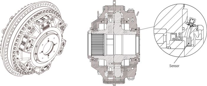
Magnetic plug
General
A magnetic plug is pre assembled in the Hägglunds CBm from factory. By regularly inspecting the magnetic plug a malfunction of the hydraulic system can be detected and corrected. The magnetic plug can also be used for early detection of wear or spall damages in the motor. The magnetic plug is installed in connection T8, in the drain outlet D3. If other drain outlet is used (D1-D2, D4-D8), the magnetic plug should be moved to the connection (T7 or T9) in the selected drainage.
Magnetic plug mounted on CBm 2000

| 1 | T8, Magnetic plug |
| 2 | Flushing inlet |
For inspection and maintenance routines, see Installation and maintenance manual: RE 15300-WA.
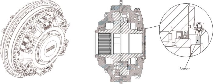
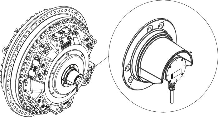
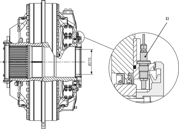
Temperature sensor
Function
The temperature sensor is mounted in the motor case and operates according to the hydraulic fluid temperature variation. The sensor element is a Pt100 resistance sensor, which change resistance in relation to the fluid temperature in the motor case.
Technical data, Pt 100/4-20 mA sensor
Material ID: R939005085 Temperature sensor
Item number: 577 7112-083 Temperature sensor
Technical data, Pt 100/4-20 mA sensor
| Sensor length l | mm | 60 |
| Process connection | G 1/4“ 100 | |
| Degree of protection | IP65 | |
| Type of sensor element | Pt 100 | |
| Output | 4 ... 20 mA/0 ... 100 ºC | |
| Connector | DIN 43650 screw terminals | |
| Cable connection | Pg9 cable Ø6 ... 8 mm | |
| Electrical connection | 2-wire connection | |
| Connection | Pin 1 – Ub Pin 2 – 4 ... 20 mA output | |
| Supply voltage Ub | V DC | 7,5 … 30 |
| Reverse polarity protection | yes | |
| Max, load | 750 W at 24 V ((Ub - 7.5 V)/0.022) |
Temperature sensor
Dimensions in mm
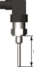
Temperature sensor
| 1) | Temperature sensor |
Painting system
Corrosion protection
The painting system of Hägglunds motors and accessories are available in two different corrosivity categories regarding corrosion protection in accordance with SS-EN ISO 12944:
- C3 - Corrosivity category Medium - which is recommended for normal urban and industrial atmosphere.
- C5M - Corrosivity category Very High - which is recommended for marine environment with high salt load or other aggressive atmosphere.
Colour
Standard colour for Hägglunds motors and accessories is orange (RAL 2002)
Type of seal
Option N:
NBR (Nitrile) Preferred alternative at low ambient temperatures and moderate case oil temperatures.
See Table "General data".
Option V:
FPM (Viton) Preferred alternative at higher case oil temperatures and freewheeling at higher speed or operating with fire resistant fluids. See Table "General data", section "Power loss freewheeling" and Table "Operating with fire resistant fluids".
Increased robustness
Option A:
CBm has DLC-coated pistons and piston rings as standard. That give no limitation for low speed even down to 0.03 rpm at maximum pressure.
Option C:
If there is a risk for cavitation in combination with shock loads and/or low oil viscosities below 20 mm2/s in motor case, there is an option to also have DLC-coated cam rollers.
Through hole kit
This device makes it possible to flush through the driven shaft or to draw electric cables through the motor. The through hole kit is prepared for rotation speed sensor.
Dimension drawing
See chapter "Information" – Table "Related documents"
Ordering code
See ordering code for Hägglunds CBm in chapter "Type Code".
Example: Hägglunds CBm 2000 with Through hole kit
Dimensions in mm
| 1 | V-ring |
| 2 | For oil lubrication of spline G 1/4 (4x) |
| 3 | O-ring |
| 4 | L1 with through hole |
| Motor | L1 |
| mm | |
| CBm 2000 | 856 |
| CBm 3000 | 973 |
| CBm 4000 | 1091 |
| CBm 5000 | 1210 |
| CBm 6000 | 1328 |
Symbols/Circuit diagrams
Circuit design
Closed circuit

Things to consider:
- Level of charge pressure.
- Requirement of bleed off feature.
- Flushing of motor case and pump case when needed.
- Filter between motor and pump.
- Cooler in the return line.
Open circuit

Things to consider:
- Counter pressure required minimum 2 bar to ensure piston function.
- Cross relief valves for blocked protection.
- Anticavitation valves to ensure piston function.
- Return line filter.
- Case drain circulation
- Cooler in the return line
Dimensions
Dimensions CBm 2000
| D1 | Pitch diameter | mm | 1380 | |
| D2 | Outer diameter | mm | 1460 | |
| D4 | Guide diameter | mm | 1300 | |
| D5 | Spline size | DIN 5480 | N360 x 8 x 30 x 44 x 9H | |
| L1 | Total length | Without through hole | mm | 855 |
| L2 | Length to hollow shaft | mm | 416 | |
| L3 | Length to spline end | mm | 171 | |
| L4 | Length to spline | mm | 346 | |
Dimensions CBm 3000
| D1 | Pitch diameter | mm | 1380 | |
| D2 | Outer diameter | mm | 1460 | |
| D4 | Guide diameter | mm | 1300 | |
| D5 | Spline size | DIN 5480 | N440 x 8 x 30 x 54 x 9H | |
| L1 | Total length | Without through hole | mm | 965 |
| L2 | Length to hollow shaft | mm | 409 | |
| L3 | Length to spline end | mm | 171 | |
| L4 | Length to spline | mm | 346 | |
Dimensions CBm 4000
| D1 | Pitch diameter | mm | 1380 | |
| D2 | Outer diameter | mm | 1460 | |
| D4 | Guide diameter | mm | 1300 | |
| D5 | Spline size | DIN 5480 | N440 x 8 x 30 x 54 x 9H | |
| L1 | Total length | Without through hole | mm | 1083 |
| L2 | Length to hollow shaft | mm | 527 | |
| L3 | Length to spline end | mm | 289 | |
| L4 | Length to spline | mm | 464 | |
Dimensions CBm 5000
| D1 | Pitch diameter | mm | 1380 | |
| D2 | Outer diameter | mm | 1460 | |
| D4 | Guide diameter | mm | 1300 | |
| D5 | Spline size | DIN 5480 | N460 x 8 x 30 x 56 x 9H | |
| L1 | Total length | Without through hole | mm | 1201 |
| L2 | Length to hollow shaft | mm | 526.5 | |
| L3 | Length to spline end | mm | 263.5 | |
| L4 | Length to spline | mm | 463.5 | |
| L5 | Length between flanges | mm | 270 | |
Dimensions CBm 6000
| D1 | Pitch diameter | mm | 1380 | |
| D2 | Outer diameter | mm | 1460 | |
| D4 | Guide diameter | mm | 1300 | |
| D5 | Spline size | DIN 5480 | N460 x 8 x 30 x 56 x 9H | |
| L1 | Total length | Without through hole | mm | 1320 |
| L2 | Length to hollow shaft | mm | 526.5 | |
| L3 | Length to spline end | mm | 263.5 | |
| L4 | Length to spline | mm | 463.5 | |
| L5 | Length between flanges | mm | 270 | |
Mounting
Mounting alternatives
General information
With splines for flange or torque arm mounting.
The splines shall be lubricated, and filled with hydraulic oil at assembly, or filled with transmission oil from the connected gearbox. To avoid wear in the splines, the installation must be within the specified tolerances in Figure "Flange mounting for CBm 2000 to 4000".
For requriements of spline shaft, see chapter "Information" – Table "Related documents".
Flange mounted motor with splines and through hole for cooling of the driven machine
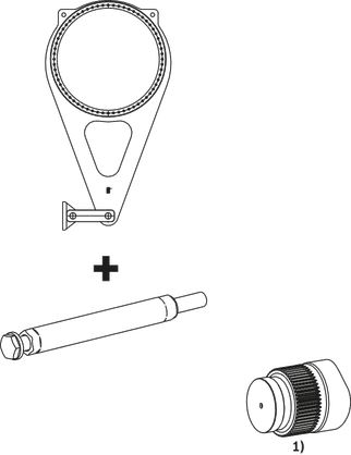
Torque arm mounted motor with splines

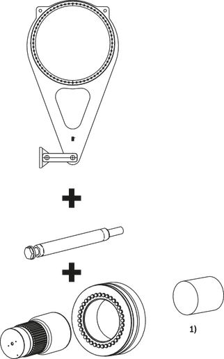
Torque arm mounted motor with coupling adapter

Flange mounted motor with splines and low radial load from driven shaft
Flange mounted motor with splines and high radial load from driven shaft
Flange mounting with splines
Flange mounting for CBm 2000 to 4000
| 1 | O-ring delivered with the motor. |
| 2 | Note! |
| 3 | For installation drawings spline shaft flange mounting, see chapter "Information" – Table "Related documents" |
Features
- Possibility to use the motor as a one side shaft support bearing.
- Oil lubrication of splines give no wear.
- Easy mounting of motor to driven shaft.
Note!
Flange mounting gives high risk for overloading of motor main bearings. Always check that the shaft and motor bearings are statically determined.
Recommended material in the splineshaft
| Drive | Steel with yield strenght |
| Unidirectional drive | Relmin = 450 N/mm2 |
| Bidirectional drive | Relmin = 700 N/mm2 |
Torque arm mounting with splines
| 1 | O-ring delivered with the motor. |
| 2 | Note! |
| 3 | Mounting kit must be ordered seperately, see chapter "Accessories" – Table "To order mounting kit" |
| 4 | Torque arm mounting, see chapter "Accessories" |
| 5 | For installation and dimensional drawings, spline shaft torque arm mounting, see chapter "Information" – Table: "Related documents" |
Recommended material in the shaft, see Table "Recommended material in the splineshaft"
Spline designation shaft, see Table "Spline designation shaft"
Submerged application
Valid for Hägglunds CBm 2000 to CBm 4000.
The motor is designed for flange mounted spline motors and submerged applications.
The dimensional drawing for design of flange, and item number for O-rings, see chapter "Information" – Table "Related documents".
Data
Max depth in water is 70 m.
To order
O-rings, see Dimension drawing submerged applications chapter "Information" – Table "Related documents".
Special index motor S-11, prepared for submerged applications.
Painting system C5M-Corrosivity category Very High.

| 1 | No water against the radial seal. |
| 2 | O-ring, see Dimension drawing submerged applications chapter "Information" – Table "Related documents" |
Information
Related documents
| Title | Document no | Document type |
| Hydraulic fluid quick reference | RE 15414 | Data sheet |
| Hägglunds CBm | RE 15300-WA | Installation & maintenance manual |
| CBM 2000 with splines | 078 2556 | Dimension drawing |
| CBM 3000 with splines | 078 2557 | |
| CBM 4000 with splines | 078 2558 | |
| CBM 5000 with splines | 078 2559 | |
| CBM 6000 with splines | 078 2560 | |
| Shaft with splines CBM 2000 | 078 2432 | |
| Shaft with splines CBM 3000-4000 | 078 2451 | |
| Shaft with splines CBM 5000-6000 | 078 2673 | |
| Through hole kit | 078 2674 | |
| Submerge applications CBM 2000-4000 | 078 2758 | |
| CBM 2000 splines, with coupling adapter | 078 2561 | |
| CBM 3000 splines, with coupling adapter | 078 2562 | |
| CBM 4000 splines, with coupling adapter | 078 2563 | |
| CBM 5000 splines, with coupling adapter | 078 2564 | |
| CBM 6000 splines, with coupling adapter | 078 2565 | |
| Tandem CBM 2000 +TBM 40 + CBP 400 | 078 2676 | |
| Torque arms Hägglunds TCA, DTCA, DTCB | RE 15355 | Data sheet |
| Rotation speed sensing unit, Hägglunds SPDC | RE 15350 | |
| Rotation speed sensing unit, Hägglunds SPDB2 EX | RE 15352 | |
| Rotation speed sensing unit, Hägglunds Inductive through hole | RE 15351 | |
| Cross-over valve, Hägglunds COCB 500, COCB 1000 | RE 15376 | |
| Counter balance valve, Hägglunds VCBCA 1000 | RE 15379 | |
| Free circulation valve, Hägglunds VFCCA 1000 | RE 15381 | |
| Four-way valve including counter balance on load line, Hägglunds V4WCA 1000 | RE 15382 | |
| Hydraulic quick stop valve, Hägglunds VQCB 800 | RE 15375 | |
| Freewheeling valve, Hägglunds VFWCB 600 | RE 15380 |
Accessories
Torque arm mounting alternatives
Torque arm mounting
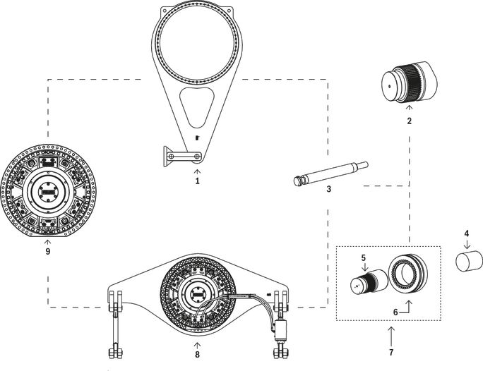
| 1 | Torque arm (Provides load on the customer machine) |
| 2 | Spline shaft on driven machine |
| 3 | Mounting kit |
| 4 | Plain shaft on driven machine |
| 5 | Adapter shaft |
| 6 | Shrink disk |
| 7 | Coupling adapter |
| 8 | Double ended torque arm (Provides no loads on the customer machine) |
| 9 | Hägglunds CBm motor |
For dimensions, techical data, order code and material ID, see separate data sheet: RE 15355
| Torque arm mounting with spline | Torque arm mounting with coupling adapter | ||||
| 
| ||||
| Features | Features | ||||
| Easy mounting i.e. no alignment problems. | Easy mounting i.e. no alignment problems. | ||||
| Quick mounting of motor to driven shaft. | Quick mounting of motor to driven shaft. | ||||
| Robust torque-transmitting. | Simplified machining of customer shaft. | ||||
| Controlled external forces on driven shaft. | Controlled external forces on driven shaft. | ||||
| Space saving. i.e. close mounting to the driven machine. | |||||
| 
| ||||
| Features | Features | ||||
| Easy mounting i.e. no alignment problems. | Easy mounting i.e. no alignment problems. | ||||
| Quick mounting of motor to driven shaft. | Quick mounting of motor to driven shaft. | ||||
| Robust torque-transmitting. | Simplified machining of customer shaft. | ||||
| Reduction of external forces on driven shaft. | Reduction of external forces on driven shaft. |
Coupling adapter
The coupling adapter includes shrink disk and adapter shaft.
Mounting kit must be ordered separately.
The coupling adapter is designed only for torque arm mounting.
Motor with coupling adapter
| 1 | Note! |
| 2 | Mounting kit, must be ordered separately |
| 3 | O-ring delivered with the motor. |
| 4 | Adapter shaft |
| 5 | Shrink disk |
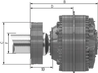
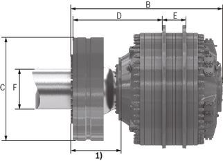
Dimensions motor with coupling adapter
Maßangaben in mm
 |  |
| CBm | CBm 2000 |
 |  |
| CBm 3000 | CBm 4000 |
 | 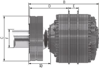 |
| CBm 5000 | CBm 6000 |
| 1) | Rotating part |
Dimensions motor with coupling adapter
| Motor | A | B | C | D | E | F | Weight |
| mm | mm | mm | mm | mm | mm | kg | |
| CBm 2000 | 1460 | 1211 | 720 | 773 | - | 360 | 4850 |
| CBm 3000 | 1419 | 950 | 863 | 460 | 6600 | ||
| CBm 4000 | 1537 | 981 | 7450 | ||||
| CBm 5000 | 1739 | 1180 | 1030 | 270 | 480 | 9700 | |
| CBm 6000 | 1857 | 10500 |
Dimensions and material for shaft end, plain shaft
Shaft end, normally loaded
Dimensions in mm
Design of driven shaft end on normally loaded shaft
In drives with only one direction of rotation and/or load where the stresses in the shaft are moderate, the shaft can be plain.
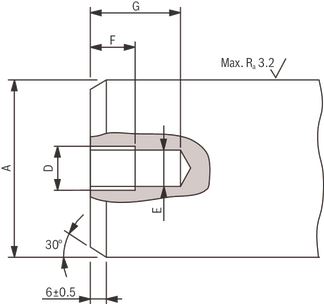
Shaft end, heavily loaded
Dimensions in mm
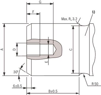
| 1) | Stressrelieving groove |
Design of driven shaft end on heavily loaded shaft
Where the driven shaft is heavily loaded and is subject to high stresses, for example for changes in the direction of rotation and/or load, it is recommended that the driven shaft should have a stress relieving groove.
Shaft recommendations
| Motor | ØA | ØA | B | C |
| Tolerance | ||||
| mm | mm | mm | mm | |
| CBm 2000 | 360 | - 0.018 - 0.075 | 257 | 354 |
| CBm 3000 | 460 | - 0.02 - 0.083 | 300 | 454 |
| CBm 4000 | ||||
| CBm 5000 | 480 | 320 | 474 | |
| CBm 6000 |
Note! The dimensions are valid at 20 °C
Threads for assembly tool (plain shaft)
| Measures | Dimensions, threads for assembly tool | |
| D | M20 | UNC 5/8" |
| E | >17 mm | >13.5 mm |
| F | 25 mm | 22 mm |
| G | 50 mm | 30 mm |
Recommended material in the shaft
| Drive | Steel with yield strenght |
| Unidirectional drive | Relmin = 300 N/mm2 |
| Bidirectional drive | Relmin = 450 N/mm2 |
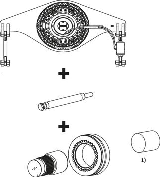
Hägglunds tandem motors
A Tandem motor consists of 3 major units, Front motor + Tandem kit TBM xx + Rear motor. On the stamping sign on the Tandem kit, the max pressure and the total weight for the complete unit are declared. Note that the complete Ordering code for a Tandem motor, contains of 3 individual Ordering codes (3 parts).
Dimensions drawings:
CBm 2000 + TBM 40 +CBP 400: See chapter "Information" – Table "Related documents".
Stamping for TBM-unit

| A | TBM-type, same as Ordering code |
| B | Week of assembly (yy-ww) |
| C | Total weight of the assembly |
| D | Max working pressure for the assembly |
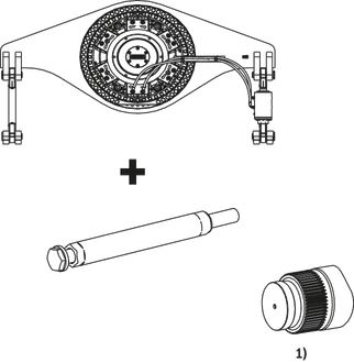
Example for torque arm mounting, CBm 2000 XXXX SB0X0A XX XX + TBM 40 0 00 00 + CBP 400 XXX SA0V00F XX XX+ Mounting kit R939055413
Dimensions in mm
| 1 | CBm 2000 XXX SB0XA XX XX |
| 2 | TBM 40 0 00 00 (No through hole) |
| 3 | CBP 400 XXX SA0V00F XX XX |
| 4 | Note! |
| 5 | Mounting kit must be ordered seperately, see Table "To order mounting kit" |
| 6 | For installation and dimensional drawings, spline shaft torque arm mounting, see chapter "Information" – Table: "Related documents" |
| Tandem motor | Max. Pressure | Total weight | A Length | Max. torque to driven shaft |
| bar | kg | mm | Nm | |
| CBm 2000 + TBM 40 +CBP 400 | 350 | 6505 | 1845 | 840000 |
| CBm 3000 + TBM 40 +CBP 400 | 7437 | 1963 | 1190000 | |
| CBm 4000 + TBM 40 +CBP 400 | 8320 | 2081 | 1540000 | |
| CBm 5000 + TBM 40 +CBP 400 | 9140 | 2199 | 1890000 | |
| CBm 6000 + TBM 40 +CBP 400 | 10005 | 2317 | 2240000 |
Speed sensor – Hägglunds CBm with SPDC
No through hole
With through hole
For technical data, see document nr: RE 15350
Features
- Slim design fully integrated in motors
- Non-contact, wear free sensing system
- Possibility to read directions of rotation from sensor
- 4544 pulses per revolution for good speed control possibility
- Protection class IP67
Description
Speed sensing unit, Hägglunds SPDC, is a digital incremental encoder using magnetic sensing technology.
The sensor generates two square wave signals with 90°phase shift for detection of speed and direction of rotation.
Speed sensor – Explosion proof speed sensor SPDB 2
SPDB 2
For technical data, see document nr: RE 15352
Features
- ATEX/IECEx approved
- 1000 and 3600 pulses per revolution for good speed control possibility.
- Possibility to read directions of rotation from sensor
- Sensor is equipped with zero pulse
- Protection class IP65
- Optional cable set with juction box to simplify connection R939003770
Description
Digital incremental hollow shaft sensor with torque arm mounting.
Recommendations:
1000 pulses for speed 6 rpm and above.
3600 pulses for speed below 6 rpm.
Speed Sensor – Inductive speed sensor SPDE with through hole unit
Inductive speed sensor SPDE with trough hole unit
Dimensions in mm
| 1) | Inductive speed sensor SPDE |
For technical data, see document RE 15351
Features
- Non-contact, wear free system
- Robust design
- ATEX/IECEx -version available
- Through hole version available
Description
Two types of sensors are available.
- The standard type has a PNP output for direct driving of load or digital input.
- The ATEX/IECEx type (explosion proof) needs an isolation amplifier outside explosive area.
The sensor is mainly intended for speed indication.
Direction of rotation cannot be indicated.
Mounting is done by replacing a plug on the motor with the sensor and tighten to 35 Nm.
To order:
|
| Material ID | Item Number |
| Standard type | R939002764 | 078 0238-802 |
| ATEX/IECEx type | R393054489 | 078 0271-801 |
Valves
Cross-over valves, COCB 1000-1, -3

For technical data, see document nr: RE 15376
Features
- Compact and robust design
- Mounted directly on Hägglunds motors
- Protect the motor from high pressure peaks
- Provides cavitation protection
- Oil exchange for closed loop system
The valve COCB is designed for Hägglunds motors and provides cross-line relief at pressure shocks and cavitation protection. The relief valves have a standard setting of 350 bar but can be delivered with preset pressure levels down to 280 bar in steps of 10 bar. Pressure setting is made without charge pressure. The charge pressure relief valve (COCB 1000-3) has a standard setting of 15 bar but is adjustable down to 3 bar.
Hydraulic circuit COCB 1000 1
Counter balance valve, VCBCA 1000

For technical data, see document nr: RE 15379
Features
- Compact and robust design
- Mounted directly on Hägglunds motors
- Counter balance function with low pilot pressure
- Pilot pressure independent of load pressure
The VCBCA valve is designed for Hägglunds motors and provides counter balance functions on the motor high pressure line and straight through connection on the motor low pressure line. The maximum operating pressure is 350 bar and maximum flow 1000 l/min.
Hydraulic circuit VCBCA 1000 00 00

Free circulation valve with freewheeling, VFCCA 1000

For technical data, see document nr: RE 15381
Features
- Compact and robust design
- Mounted directly on Hägglunds motors
- Free circulation function with minimal pressure drop
- Free circulation shift allowed up to 40 rpm
- Freewheeling function
- Shifting from drive operation into freewheeling allowed up to 10 rpm
The VFCCCA valve is designed for Hägglunds motors and provides free circulation or freewheeling functions. The maximum operating pressure is 350 bar and maximum flow 1000 l/min.
The valve is available in two configurations:
VFCCA 1000 H Free circulation valve Hydraulic operated
VFCCA 1000 E Free circulation valve Electric operated 24 VDC
Four-way valve, V4WCA 1000

For technical data, see document nr: RE 15382
Features
- Compact and robust design
- Mounted directly on Hägglunds motors
- Four way directional and flow control of motor
- Proportionally controlled flow of the motor
- Counter balance function on motor pressure line
The V4WCA valve is designed for Hägglunds motors and provides four way directional and flow control of the motor. The flow is controlled proportional by external pilot pressure applied to ports X1 and X2. The valve includes a counter balance function on the motor pressure line. Maximum operating pressure is is 350 bar and maximum flow 1000 l/min.
The valve is available in one configuration:
V4WCA-1000 including adapter
Hydraulic quick stop valve, VQCB 800

For technical data, see document nr: RE 15375
Features
- Compact and robust design
- Mounted directly on Hägglunds motors
- Fast response time
The VQCB 800 valve is designed for Hägglunds motors and provides quick stop for a roll mill rolls without stopping the electric motor and without any need of mechanical brake. A very short braking time is possible due to the small moment of inertia and quick response from hydraulic valve. Maximum operating pressure is 350 bar and maximum flow 800 l/min.
Hydraulic circuit VQCB 800

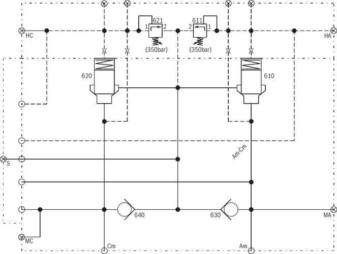
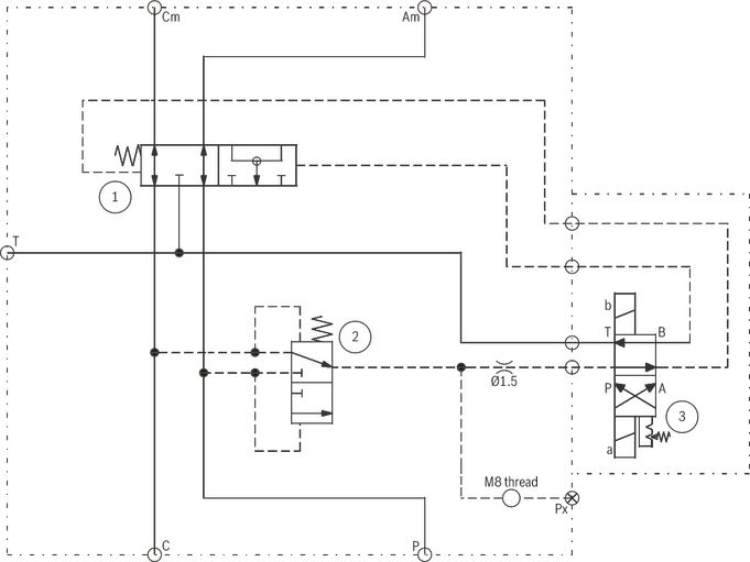
Freewheeling valve VFWCB 600

For technical data, see document nr: RE 15380
Features
- Compact and robust design
- Multifunctional
- Mounted directly on Hägglunds motors
- Detent function on pilot valve
- Possible for remote control
The VFWCB 600 valve is designed for Hägglunds motors and provides freewheeling of the motor by means of disconnecting the motor from the main lines and connect both motor ports to T which has to be drained to tank. The valve can be mounted directly onto the motor via an adapter and can be used in both open and closed loop applications. Maximum operating pressure is 350 bar and maximum flow 1000 l/min. Nominal flow is 600 l/min.
The valve is available in three main configurations:
VFWCB 600 E Freewheeling valve electrically operated
VFWCB 600 H Freewheeling valve hydraulically operated
VFWCB 600 M Freewheeling valve manually operated
Hydraulic circuit VFWCB 600
Speed sensor
Hägglunds SPDC

Speed sensor
Hägglunds SPDC
- Valid for:
• Hägglunds CA
• Hägglunds CA with BICA
• Hägglunds CB
• Hägglunds CBP
• Hägglunds CBM
Speed sensor, explosion proof
Hägglunds SPDB 2 with mounting set

Speed sensor, explosion proof
Hägglunds SPDB 2 with mounting set
- Valid for: Hägglunds motors CA, CB, CBP and CBM
Single ended torque arms
Hägglunds TCA

Single ended torque arms
Hägglunds TCA
- Valid for: Hägglunds motors CA, CB, CBP and CBM
Hydraulic quick stop valve
Hägglunds VQCB 800

Hydraulic quick stop valve
Hägglunds VQCB 800
- Valid for Hägglunds CA, CB, CBP, CBM
- Maximum flow 800 l/min
- Fast response time, i.e. 100 ... 150 ms
- Maximum pressure 350 bar
- Open and closed loop
Cross-over valve
Hägglunds COCB 700, COCB 1000
Includes valves for ATEX environment

Cross-over valve
Hägglunds COCB 700, COCB 1000
Includes valves for ATEX environment
- Valid for: Hägglunds motor CA, CB, CBM
- Maximum flow 700 l/min, 1000 l/min
- Maximum pressure 350 bar
- Open and closed loop hydraulic system
Counter balance valve
Hägglunds VCBCA 1000

Counter balance valve
Hägglunds VCBCA 1000
- Valid for: Hägglunds motor CA, CB, CBM
- Maximum flow 1000 l/min
- Maximum pressure 350 bar
Freewheeling valve
Hägglunds VFWCB 600
Includes valves for ATEX environment

Freewheeling valve
Hägglunds VFWCB 600
Includes valves for ATEX environment
- Valid for: Hägglunds motor CA, CB, CBM
- Maximum flow 1000 l/min
- Nominal flow 600 l/min
- For closed and open loop hydraulic system
Free circulation valve
Hägglunds VFCCA 1000
Includes valves for ATEX environment

Free circulation valve
Hägglunds VFCCA 1000
Includes valves for ATEX environment
- Valid for: Hägglunds motor CA, CB, CBM
- Maximum flow 1000 l/min
- Maximum pressure 350 bar
- Open and closed loop hydraulic system
Four-way valve including counter balance on load line
Hägglunds V4WCA 1000

Four-way valve including counter balance on load line
Hägglunds V4WCA 1000
- Valid for: Hägglunds motor CA, CB, CBM
- Maximum flow 1000 l/min
- Maximum pressure 350 bar


Нет отзывов об этом товаре.