Артикул: RX8295
В наличии
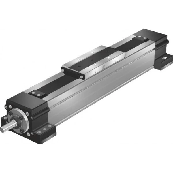
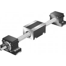
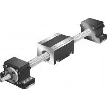
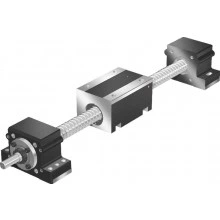
Closed-type drive units with ball screw drive AGK-032-NN-1
Цена по запросу Стоимость зависит от выбранного способа оплаты и количества товара.
Не отвечаем 5 минут — скидка на весь заказ!
Нужна скидка? Звони — сделаем лучшее предложение
Работаем по всей России
Возможны самовывоз и доставка по всей территории России
Надежность
Профессиональная поддержка
Description
Product description
Design
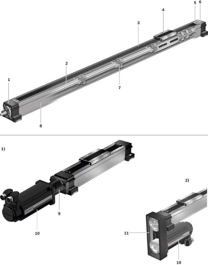
| 1) | Mount and coupling |
| 2) | Timing belt side drive |
1 Pillow block (fixed bearing)
2 Rexroth Ball Screw Assembly with clearance-free, Cylindrical Single Nut
3 Sealing strip made of steel or plastic
4 Nut housing
5 Strip fixing
6 Pillow block bearing (floating bearing)
7 Screw support (SPU)
8 Protection profile
motor mounting
9 Mount and coupling
10 Servo motor
11 Timing belt side drive
Assembly of mount and coupling
A motor can be attached to all Drive Units via mount and coupling.
The mount secures the motor to the Drive Unit and serves as a closed housing for the coupling.
The coupling transmits the motor drive torque to the Drive Unit's drive shaft without distortive stresses.
Our standard couplings compensate for the system's thermal expansion.
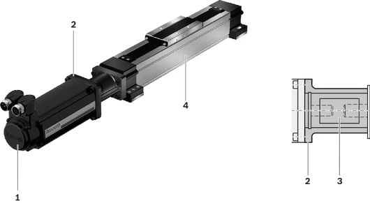
1 Motor
2 Mount
3 Coupling
4 Drive Unit
Construction of timing belt side drive
The motors of all Drive Units can be attached using a timing belt side drive.
This makes the overall length shorter than when attaching the motor with a mount and coupling.
The space-saving, closed pulley housing serves as protection for the belt and as a motor bracket.
In addition, various gear ratios are also available (depending on size):
- i = 1
- i = 2
The timing belt side drive can be mounted in four different directions:
- bottom, top (RV01 and RV02)
- left, right (RV03 and RV04)

1 Pulley housing made of anodized aluminum frame
2 Drive Unit
3 Timing belt
4 Motor
5 Timing belt pre-tensioning: Apply pre-load force Fpr to the motor (Fpr will be indicated on delivery)
6 Cover
7 Attaching the belt pulleys with tensioning units
8 Cover plate for timing belt side drive
Technical data
Note: Observe the document "Calculation" in the section "Project planning notes".
Load capacities and moments
| Size | AGK-032 | |||||
| d0 x P | mm | 32 x 5 | 32 x 10 | 32 x 20 | 32 x 32 | |
| C | Nuts | N | 23310 | 34200 | 21240 | 21060 |
| Fixed-bearing | N | 26000 | ||||
General technical data
| Size | AGK-032 | |||||
| d0 x P | mm | 32 x 5 | 32 x 10 | 32 x 20 | 32 x 32 | |
| Lc | mm | 204 | ||||
| Lad with number of screw supports | 0 | mm | 86 | |||
| 1 | mm | 201 | ||||
| 2 | mm | 326 | ||||
| 3 | mm | 451 | ||||
| smin 1) | mm | 150 | ||||
| Lmax | mm | 5000 | ||||
| mca | kg | 3.5 | ||||
| kg fix | kg | 4.7 | ||||
| kg var | kg/mm | 0.0099 | ||||
| 1) | Minimum travel to ensure a reliable lubrication distribution. |
Calculation of the mass of the linear motion system
(without motor attachment, without motor)

Length calculation

Effective stroke

Drive data
| Size | AGK-032 | |||||
| d0 x P | mm | 32 x 5 | 32 x 10 | 32 x 20 | 32 x 32 | |
| kJ fix | kg·mm² | 131.7 | 138.4 | 165 | 220.3 | |
| kJ var | kg·mm | 0.7117 | 0.6668 | |||
| kJ m | mm² | 0.633 | 2.533 | 10.132 | 25.938 | |
| MRs with number of screw supports | 0 | Nm | 1.1 | 1.2 | 1.3 | |
| 1 | Nm | 1.2 | 1.3 | 1.4 | 1.5 | |
| 2 | Nm | 1.2 | 1.4 | 1.5 | 1.7 | |
| 3 | Nm | 1.2 | 1.4 | 1.6 | 1.9 | |
| amax | m/s² | 17.9 | 30.7 | 50 | ||
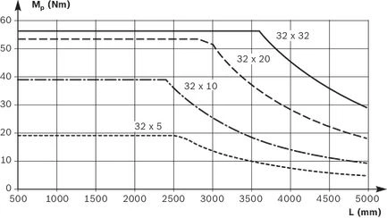
Note: For the max. drive torque Mp and max. speed vmax see section on "Diagrams / Characteristic curves".
Drive data for motor attachment using the timing belt side drive
| Size | Motor | d0 x P | up to L2) | Msd1) | Jsd | MRsd | msd | F | Bt | |||
| mm | mm | i = 1 | i = 2 | i = 1 | i = 2 | Nm | kg | mm | i = 1 | i = 2 | ||
| Nm | Nm | 10‑6 kgm2 | 10‑6 kgm2 | |||||||||
| AGK-032 | MS2N06 | 32 x 5 | 2500 | 19,10 | 9,55 | 1400 | 260 | 0,5 | 3,2 | 116 | 25 AT5 | 32 AT5 |
| 32 x 10 | 3000 | 19,21 | 12,30 | |||||||||
| 32 x 20 | 4200 | |||||||||||
| 32 x 32 | 5000 | |||||||||||
| 1) | Values for Msd without making allowance for the motor torque. |
| 2) | For greater lengths, the permissible drive torque is determined from the variable-length value Mp of the Drive Unit in accordance with the diagram. See "Project planning notes" section. |
Drive data for motor attachment via mount and coupling
| Size | Motor | Coupling | Mount and coupling | |
| McN | Jc | mfc | ||
| Nm | 10‑6 kgm2 | kg | ||
| AGK-032 | MS2N06 | 50 | 210 | 1,8 |
Normal operating conditions
| Size | AGK-032 | |
| Permissible ambient temperature with Rexroth servo motor 1) | 0 °C ... +40 °C | |
| Permissible ambient temperature for mechanical system 2) | -10 °C ... +60 °C | |
| smin 3) | mm | 150 |
| 1) | Performance losses from 40°C |
| 2) | No passing below the dew point |
| 3) | Minimum travel to ensure a reliable lubrication distribution. |
Note: Application of dirt is not permitted!
Legend
| Symbol | Description | Unit |
| amax | Maximum acceleration travel | m/s2 |
| Bt | Belt type | - |
| C | Dynamic load capacity | N |
| d0 | Nominal diameter of ball screw drive | mm |
| F | Pulley housing width | mm |
| i | Timing belt side drive gear ratio | - |
| Jc | Mass moment of inertia of the coupling | kgm2 |
| Jsd | Reduced mass moment of inertia of timing belt side drive on the motor journal | kgm2 |
| kg fix | Constant for fixed portion of the mass | kg |
| kg var | Constant for variable-length portion of the mass | kg/mm |
| kJ fix | Constant for fixed-length portion of mass moment of inertia | kgmm2 |
| kJ m | Constant for mass-specific portion of mass moment of inertia | mm2 |
| kJ var | Constant for variable-length portion of mass moment of inertia | kgmm |
| L | Length | mm |
| Lad | Additional length | mm |
| Lc | Nut Housing length | mm |
| Lmax | Maximum length | mm |
| mca | Moved mass of system | kg |
| McN | Rated torque of coupling | Nm |
| mfc | Mass of mount and coupling | kg |
| Mp | Input torque | Nm |
| MRs | Frictional torque of the system | Nm |
| MRsd | Frictional torque of timing belt side drive on the motor journal | Nm |
| msd | Mass of timing belt side drive | kg |
| Msd | Maximum permissible drive torque of the timing belt side drive | Nm |
| P | Lead | mm |
| smin | Minimum travel | mm |
| SPU | Screw support | - |
| vmax | Maximum speed | m/s |
Diagrams/characteristic curves
Permissible drive torque MP
The displayed values of Mp are valid under the following conditions:
- no radial load on the screw journal
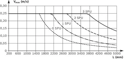
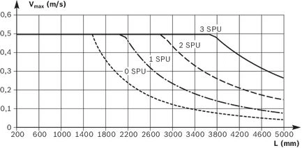
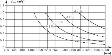
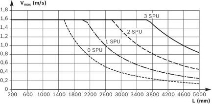
Permissible speed vmax
SPU = screw support
AGK-032 with Rexroth Ball Screw Assembly 32 x 5
AGK-032 with Rexroth Ball Screw Assembly 32 x 10
AGK-032 with Rexroth Ball Screw Assembly 32 x 20
AGK-032 with Rexroth Ball Screw Assembly 32 x 32
Fields of application
Areas of application
Drive Units can be used in many ways as a drive axis for linear motion and positioning tasks in the application areas and industries below.
Possible applications
- pick and place
- handling systems
- placers, palletizers
- feeder units for machine tools
- testing and analysis systems
- feeder units in transfer lines
- offset slide mechanisms
Possible industries
- handling and assembly
- electronics and semiconductor industry
- automotive suppliers and manufacturers
- robotics and automation
- special machinery
- packaging technology
- plastics processing
- textile industry
Application-related notes
AOK and AGK Drive Units are designed for drive tasks only and can only absorb axial forces.
When using a Drive Unit, always make sure to include adequate, separate linear guides that can handle the structure being moved as well as the resulting reaction forces and torques.
This results in a linear motion unit (e.g. table top) that can be moved automatically thanks to an AOK or AGK Drive Unit.
Examples
Example of basic motion unit structure with table top and AOK Drive Unit

In this example, two separate linear guides, each with two Runner Blocks, absorb forces and torques so that when moving the structure only axial forces act on the Drive Unit (here AGK).

Follow the assembly instructions and installation tolerances in the "Installation" section.
Dimensions
All dimensions in mm. Drawings not to scale.
Straightness and flatness tolerance according to DIN EN 12020-02
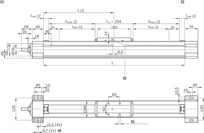
| 1) | Fixed bearing end |
| 2) | Floating bearing end |
| 3) | Lubrication hole on both sides of Nut Housing funnel-type lube nipple DIN 3405-A M6 |
| 4) | pre-drilled for pin hole |
| 5) | M10 – 15 deep (4x) |

| 1) | M8 - 15 deep (4x) |
| 2) | Reference edges on two sides |
| 3) | Slot for switch |
| 4) | min. 3 mm |
| 5) | min. 6.3 mm |
Lad = Längenzuschlag (siehe Kapitel „Technische Daten“)
Project planning information
Calculation example
Mounting
load errorCommissioning
load errorMaintenance
load errorDelivery notes
load errorSafety Instructions
load errorMotor attachment
load errorMeasurement and test reports
load errorDownloads
 | Declaration of Incorporation for single axis Linear Motion Systems Certificate | R320103141 | 2020-06-01 | All languages | PDF | 409k Product Groups: Linear axes and electromechanical cylinders |
| Safety Instructions for Linear Motion Systems Manual | R320103152_en | 2015-01-01 | English | PDF | 593k Product Groups: Linear axes and electromechanical cylinders |
| Drive Units AGK Manual | R320103986 | 2005-11-01 | English, French, German, Italian | PDF | 3.1MB Product Groups: Drive Units |
| Drive Units with Ball Screw Drives Catalog | R999001326 | 2017-06-01 | English | PDF | 13.8MB Product Groups: Drive Units |
Отзывы о товаре
Аналогичные товары
Официальный поставщик Bosch Rexroth
Продажи на территории России
Оптовые и розничные продажи
Снижение логистических расходов
Индивидуальные условия
Выгода без посредников
Единая система поставок
Весь ассортимент на складе