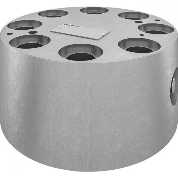
Артикул: RX7289
В наличии
2-way cartridge valves, directional functions LFT . D (high-pressure)
Цена по запросу Стоимость зависит от выбранного способа оплаты и количества товара.
Не отвечаем 5 минут — скидка на весь заказ!
Нужна скидка? Звони — сделаем лучшее предложение
Работаем по всей России
Возможны самовывоз и доставка по всей территории России
Надежность
Профессиональная поддержка
Description
- High-pressure series
- Size 16 … 63
- Component series 3X
- Maximum operating pressure 1000 bar
- Maximum flow 3500 l/min
Features
load errorProduct description
2-way cartridge valves are elements that have been designed for a compact block design. The cartridge valve type LCT is inserted into a special receiving hole in the control block and closed by a control cover type LFT. The control cover establishes the connection between the spring chamber of the cartridge valve and the pilot control valves. This enables implementation of pressure, directional and throttle functions – also in combination.
The main components of 2-way cartridge valves are the cartridge valve (8) and the control cover (2) with different functionality.
The cartridge valve (8) consists of a socket (3) with sealing package (4), control spool (5) and closing spring (6).
The control cover (2) seals the cartridge valve to the outside.
Besides simple control cover functions with external pilot oil supply, version "LFT . DBW2" is also suitable for complex switching functions thanks to its default directional valve connection surface. The connection surface is always closed pressure-tight (1). Suitable switching and proportional servo valves can be connected.
The relief pressure is set at the cartridge (7).
Due to structural-inherent requirements, some control cover versions feature high-pressure fittings leading to the outside. These are assigned a leakage bore L for indication of leakage at the HP fitting.
These ports are not suitable for external pilot oil supply.
Function
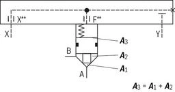
Passively controlled 2-way cartridge valves operate depending on the pressure ratio at working ports A and B. This results in three important pressurized surfaces for the function A1, A2, A3. The area at the valve seat A1 is defined as 100%. Depending on the version, the annulus area A2 realized by grading is 0%, 7% or 50% of area A1. The area A3 is identical to the sum of areas A1 + A2.
At pressure function, the area is A2 = 0. Respectively, the area is A3 = A1.
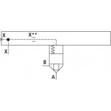
For check valve circuits, a 7% control spool with internal pressure feedback is available This way, the set-up of the block becomes less complex as external pressure feedback into the spring chamber via the pilot oil port X is not required (see "Circuit examples")
In general, the following applies:
The areas A1 and A2 are effective in opening direction. The area A3 and the spring are effective in closing direction. The direction of action of the resulting force from the opening and closing forces determines the working position of the 2-way cartridge valve.
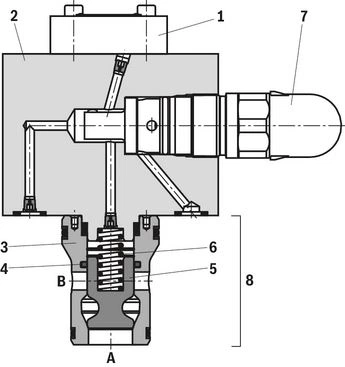
| Example: Control cover: Type LFT 25 DBW2-3X/1000J3F Cartridge valve: Type LCT 25 DB40D-3X/700F |
Type code
load errorTechnical data
general
| Size | 16 | 25 | 32 | 40 | 50 | 63 | ||
| Ambient temperature range | NBR seals | °C | -30 … +60 | |||||
| FKM seals | °C | -20 … +60 | ||||||
| MTTFD values according to EN ISO 13849 1) | Years | 150 … 1200 | ||||||
| Conformity 2) | RoHS directive | 2011/65/EU | ||||||
| 1) | For further details, see data sheet 08012 |
| 2) | The product fulfills the substance requirements of the RoHS directive 2011/65/EU. |
hydraulic
| Size | 16 | 25 | 32 | 40 | 50 | 63 | ||
| Maximum operating pressure | bar | 1000 | ||||||
| Hydraulic fluid | see table "Hydraulic fluid" | |||||||
| Hydraulic fluid temperature range | NBR seals | °C | -30 … +80 | |||||
| FKM seals | °C | -20 … +80 | ||||||
| Viscosity range | mm²/s | 2.8 … 500 | ||||||
| Maximum admissible degree of contamination of the hydraulic fluid, cleanliness class according to ISO 4406 (c) 1) | Class 20/18/15 | |||||||
| Maximum flow 2) | l/min | 3500 | ||||||
| 1) | The cleanliness classes specified for the components must be adhered to in hydraulic systems. Effective filtration prevents faults and simultaneously increases the life cycle of the components. |
| 2) | NG-dependent; see characteristic curves |
| Hydraulic fluid | Classification | Suitable sealing materials | Standards | Data sheet | |
| Mineral oils | HL, HLP, HLPD, HVLP, HVLPD | NBR, FKM | DIN 51524 | 90220 | |
| Bio-degradable | Insoluble in water | HETG | FKM | ISO 15380 | 90221 |
| HEES | FKM | ||||
| Soluble in water | HEPG | FKM | ISO 15380 | ||
| Flame-resistant | Water-free | HFDU (glycol base) | FKM | ISO 12922 | 90222 |
| HFDU (ester base) | FKM | ||||
| HFDR | FKM | ||||
| Containing water | HFC (Fuchs: Hydrotherm 46M, Renosafe 500; | NBR | ISO 12922 | 90223 | |
| Important information on hydraulic fluids:
| |||||
(For applications outside these values, please consult us!)
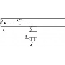
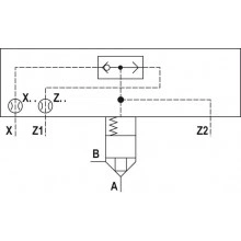
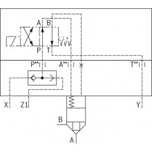
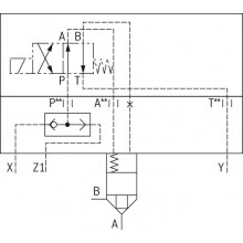
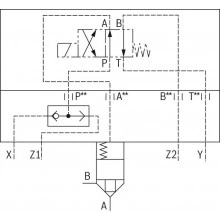
Symbols/Circuit diagrams
load errorDimensions
load errorProject planning information
load errorInformation
load errorDownloads

Отзывы о товаре
Аналогичные товары
Официальный поставщик Bosch Rexroth
Продажи на территории России
Оптовые и розничные продажи
Снижение логистических расходов
Индивидуальные условия
Выгода без посредников
Единая система поставок
Весь ассортимент на складе